INSTALLATION

STHFCT1
Comfort Roof Control Module for
v1.0
Further information and manuals for all products can be found on our web site
w w w . m o d s 4 c a r s . c o m
PLEASE READ THE COMPLETE MANUAL CAREFULLY BEFORE USING THIS PRODUCT.
INSTALLATION |
|
|
STHFCT1 Comfort Roof Control Module for v1.0 |
Further information and manuals for all products can be found on our web site w w w . m o d s 4 c a r s . c o m |
| We explicitly point out that all functions of this control unit should be used only while exercising caution and responsibility. We can NOT be held liable for any damage or injury caused by installing or using this product. PLEASE READ THE COMPLETE MANUAL CAREFULLY BEFORE USING THIS PRODUCT. |
| Important Information. READ BEFORE INSTALLING! | |
|---|---|
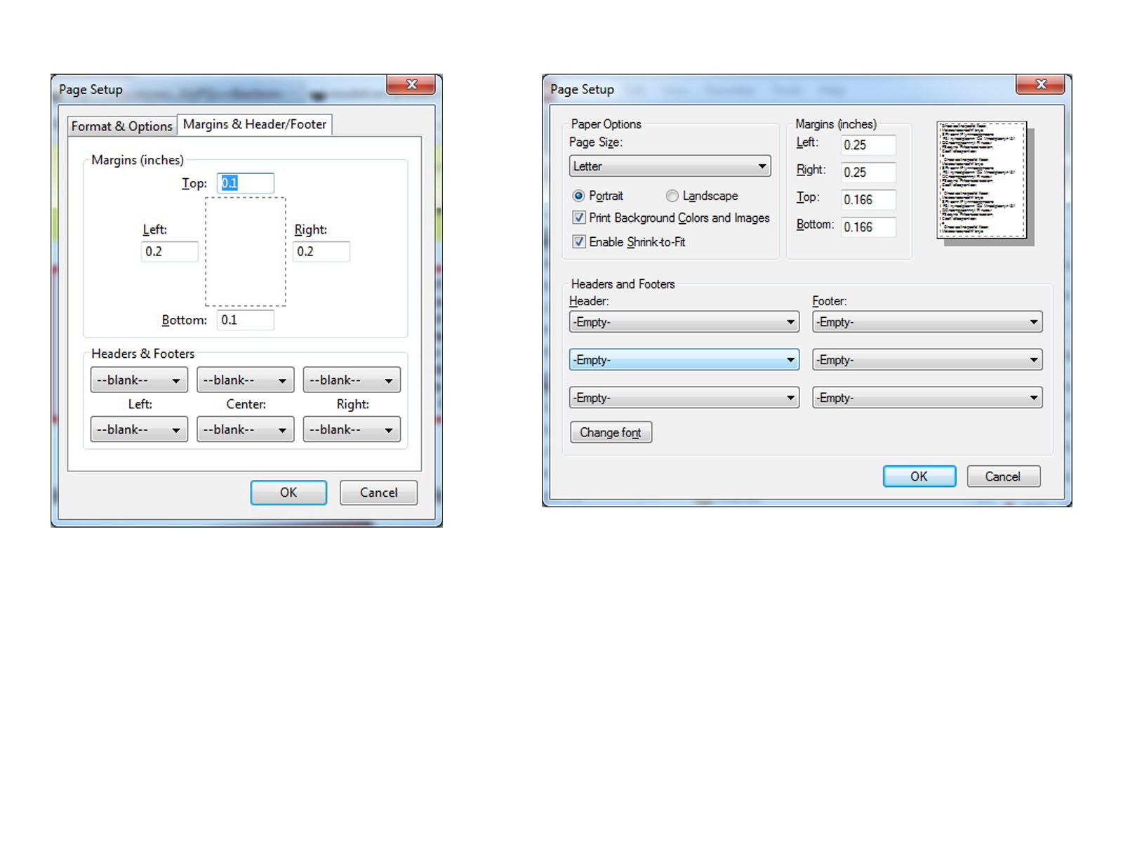
| PRINTING THIS MANUAL This manual is designed to produce completely filled pages. In order to get best print results, simply set the borders to minimum settings in the browser's page setup menu and disable headers and footers. Activate the print preview and if necessary decrease the zoom level until all pages are shown correctly. ALL IMAGES CAN BE CLICKED FOR FULL SIZE in the browser. |

| TROUBLE SHOOTING - NEED TO CONTACT US? If you run into any problems after installing the module, please go over the manual again in great detail, clicking every photo for full size! We now have a full Knowledge Base with Support Ticket system available online at www.mods4cars.com/support If you need to contact us, the best and fastest way to do so is by opening a support ticket there |

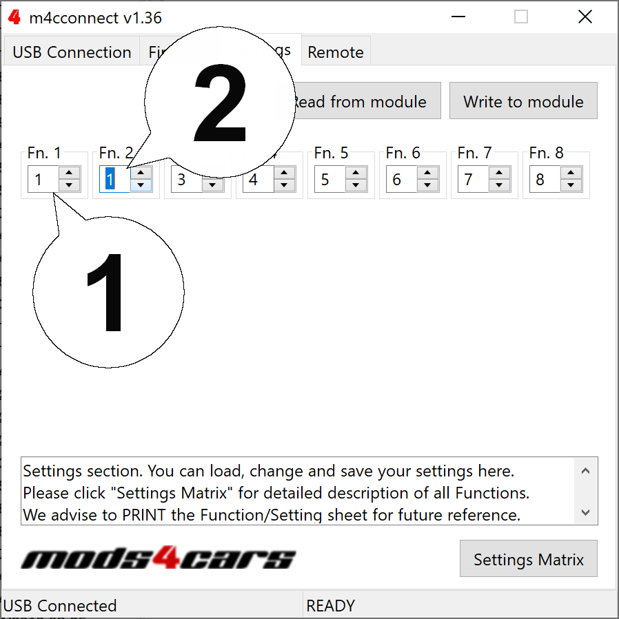
| This module comes with our USB Field Upgrade and Configuration Port! We recommend connecting it to a computer BEFORE YOU INSTALL and using our support app "m4cconnect" to do a quick firmware update check. M4cconnect as well as all other information regarding USB update and configuration can be found at www.mods4cars.com/usb. You can even configure and activate your favorite module functions and settings on screen before the module is installed in the car! It is a good idea to permanently install the USB cable with the module in the car, leaving the computer plug in an easily accessible spot for later use with a Wifi/3G/4G connected laptop. |
| IMPORTANT TROUBLESHOOTING TIPS If the top does not work properly or at all after installing the module, these tips can be very helpful: 1) Turn Function 1 (Main Switch) off (Setting 0). The module will be completely passive. If the problem still persists and the top won't work, check all connections. Please also check the green DATA LED on the module! 2) Function 2 now has a valet mode (Setting 2) on many modules. Valet mode completely disables opening of the top. Check the setting for function 2 and make sure the module is NOT in valet mode! IMPORTANT: Not all modules have the valet mode! Please check the Operation and Programming Manual! |
| Installation - Steps 1-3 | |
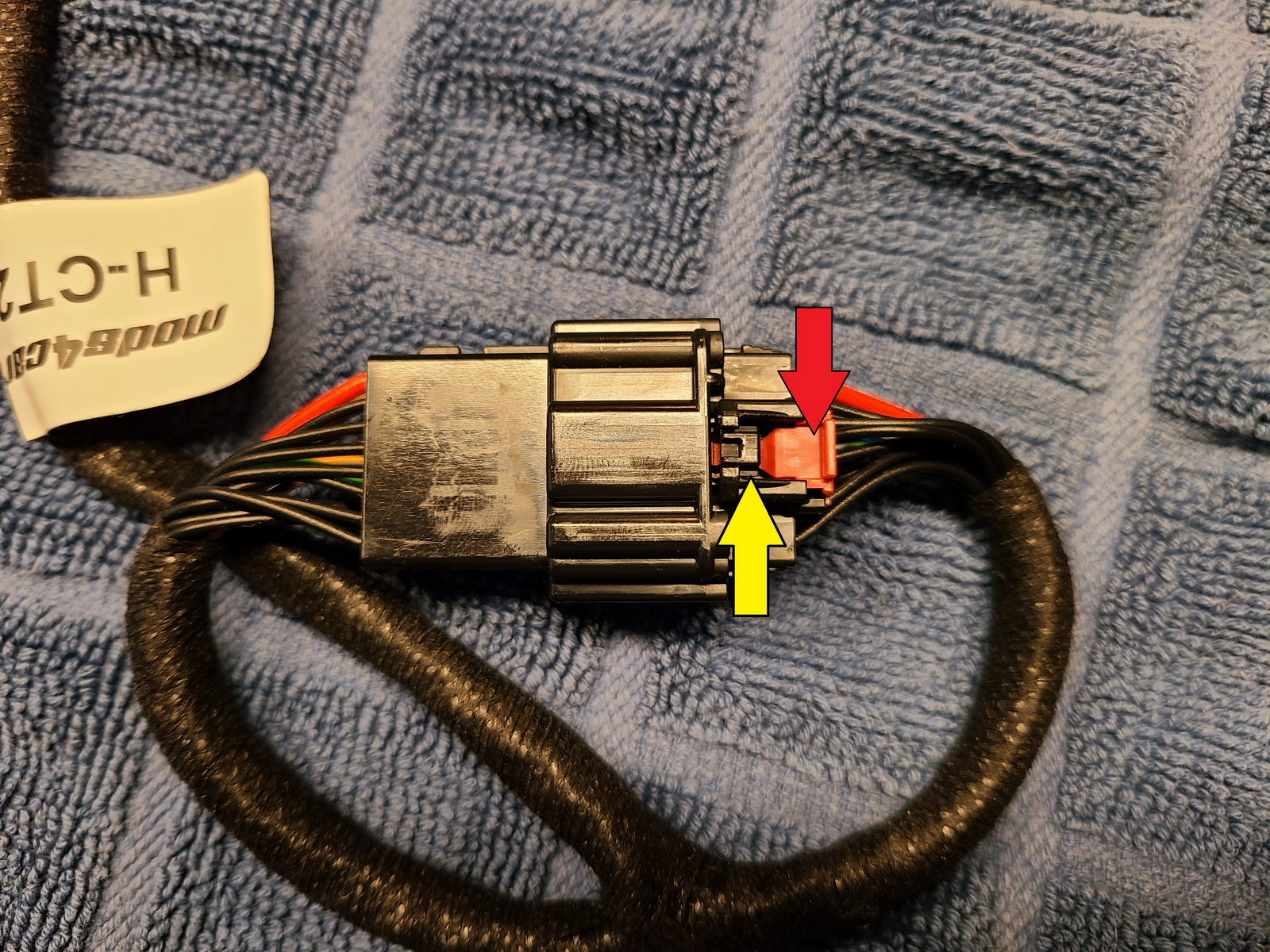
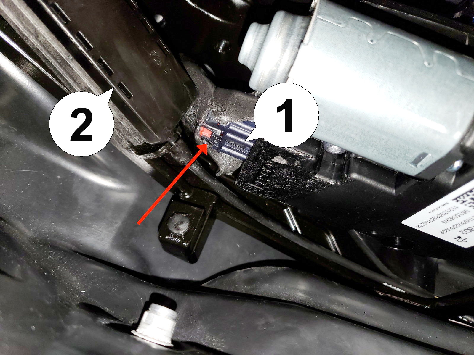
| 1. BEFORE INSTALLING: The most difficult part of the install is disconnecting the existing wiring harness connector from the top motor. We suggest taking the SmartTOP harness and connecting the two ends together, then practice disconnecting them several times until you have a feel for it. It will be harder in the confined space next to the motor, so make sure you're comfortable disconnecting them. You need to pull the red locking tab out (to the right in the image below), then press in on the black tab above the yellow arrow. Use a jeweler's screwdriver to press it. While pressing on the tab, pull the connectors apart. |
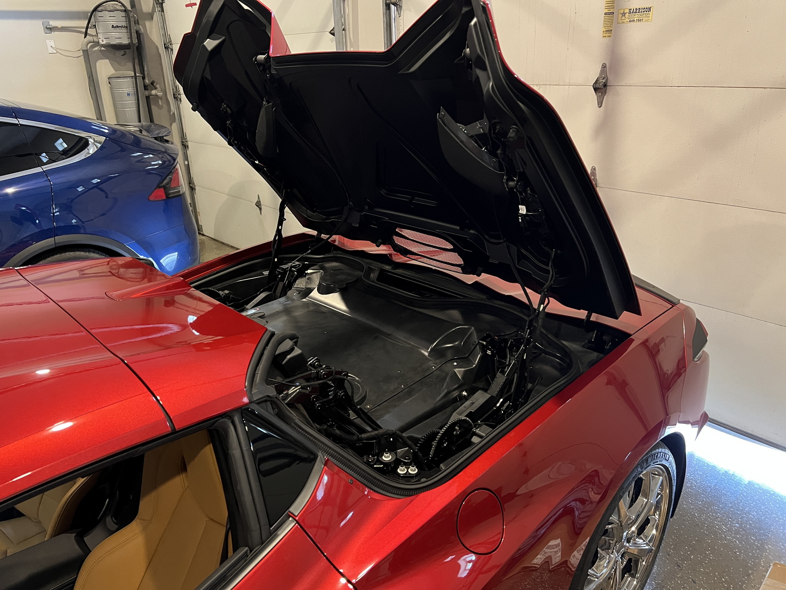
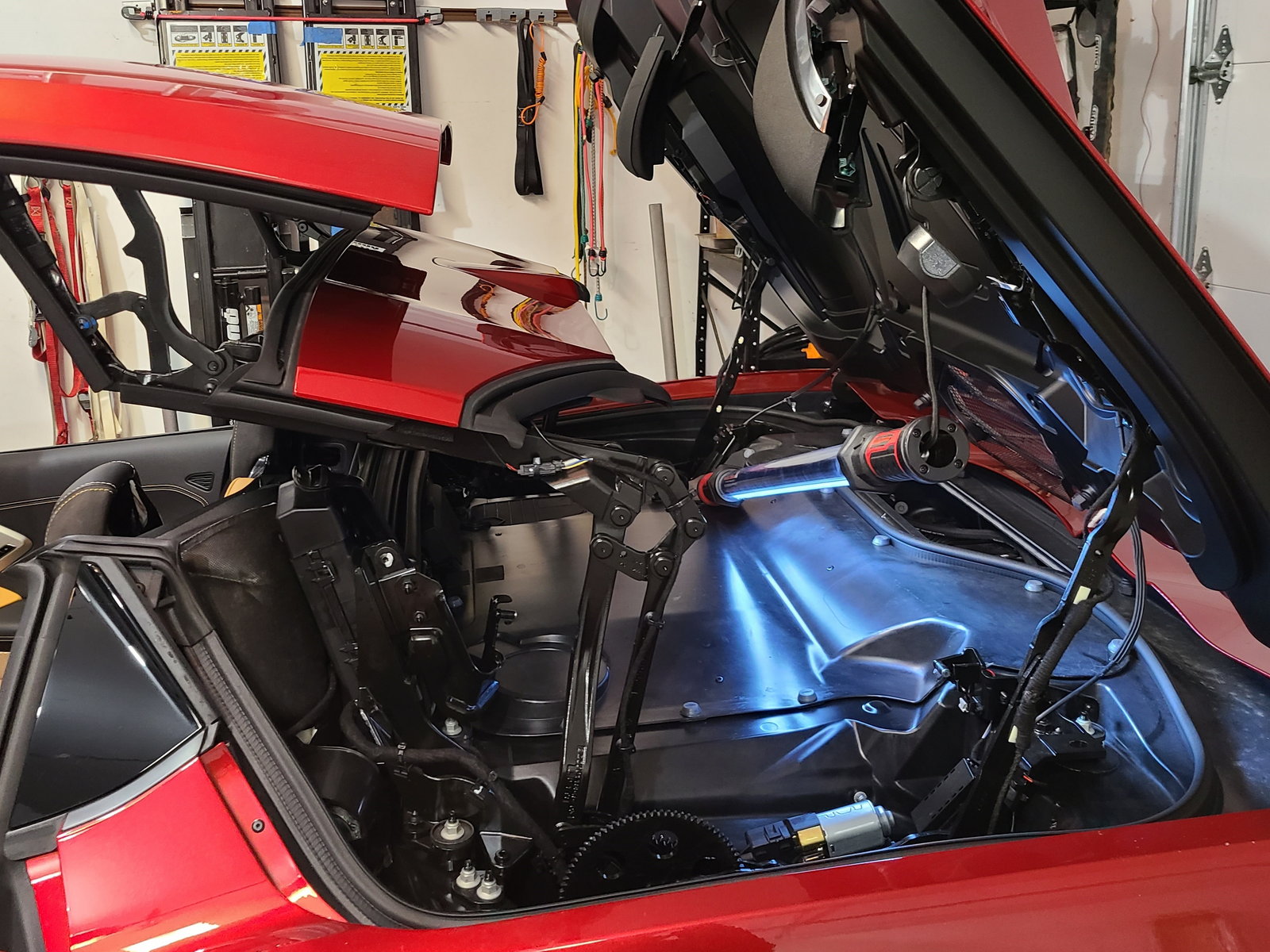
| 2. Before attempting to disconnect or install anything in the car, operate the top and tonneau in both directions, watching carefully to see where the moving parts go, especially when the tonneau closes. Do this several times. If you have a helper, have them operate the top while you watch closely (don't get your head caught under the tonneau!). If you don't have a helper, move the top and tonneau in small increments and look inside the space each time you pause. Shining a bright light on the mechanism will be helpful. When done, open the roof just until the point where the tonneau is fully standing up as shown. |
| 3. On the left side of the car (driver side on LHD cars like USA, passenger side on RHD cars like UK, AU) remove the plastic cover over the motor drive unit. |
| Installation - Steps 4-6 | |
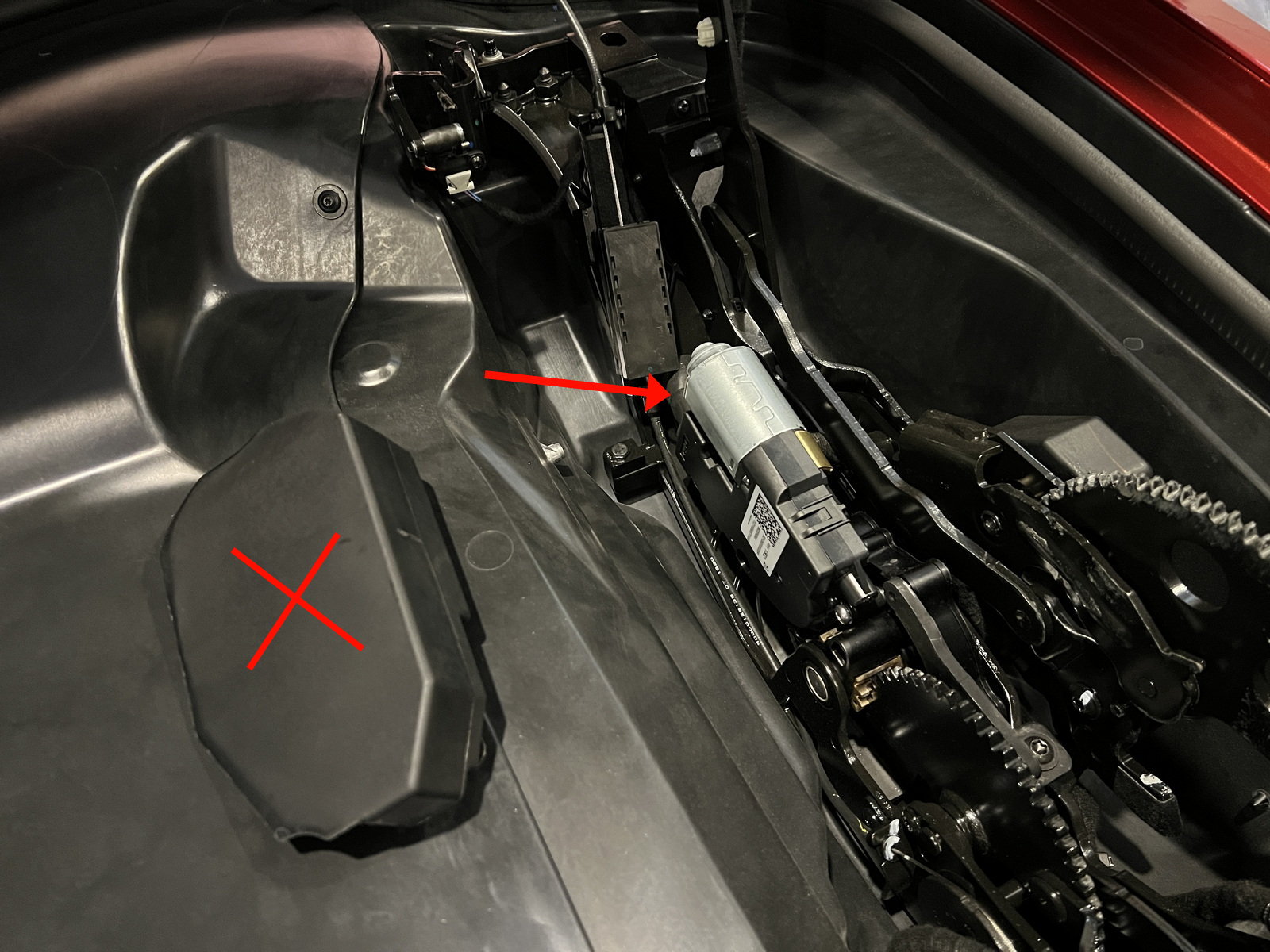
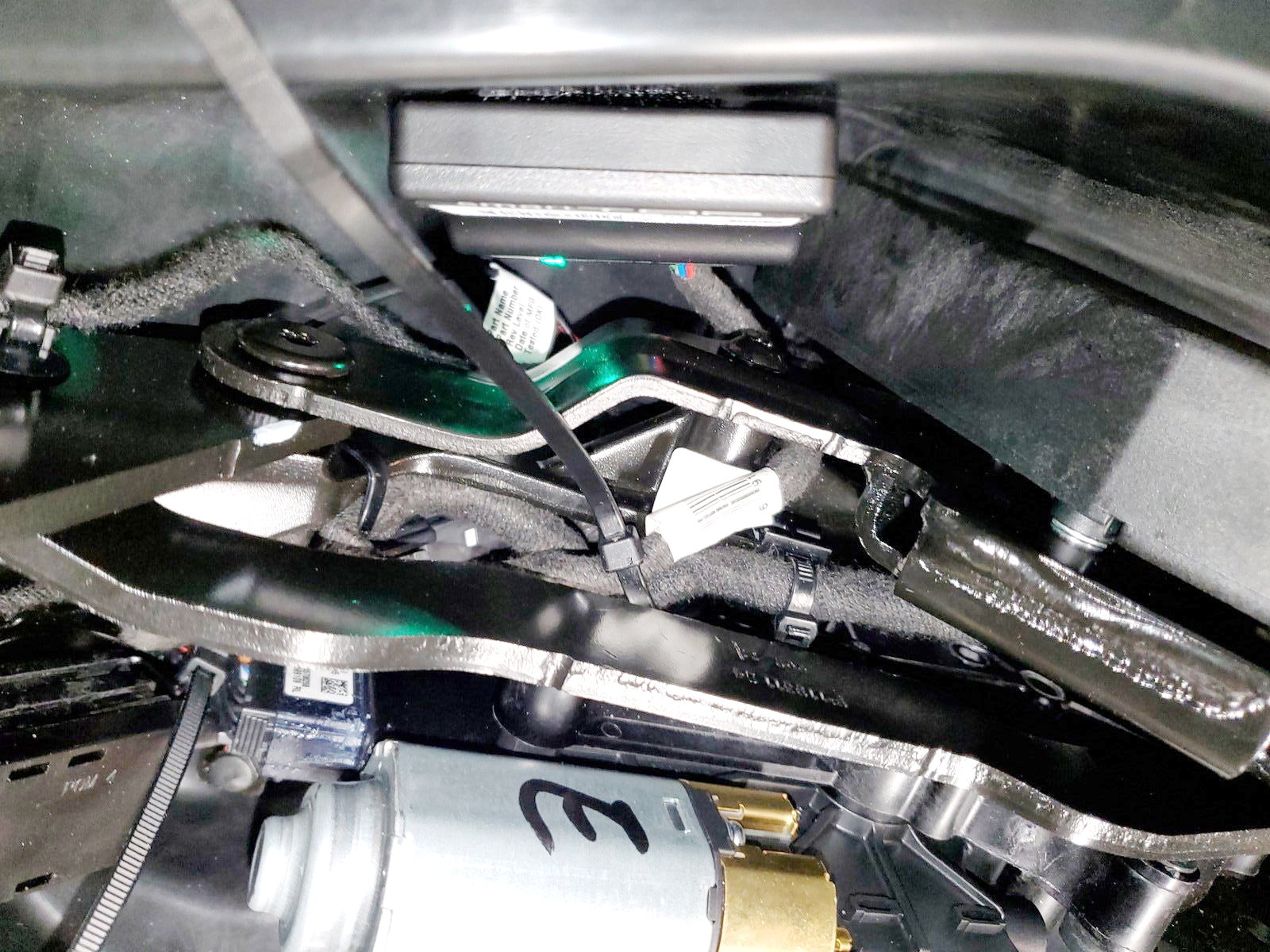
| 4. Motor drive unit with plastic cover removed. Store it outside the car in a safe spot and DO NOT leave it in the car where you could possibly forget it. Pay very close attention to the big gears and all the levers that are attached to them. Going forward you will want to make sure nothing can get pinched or jammed in the mechanical parts here. There is one connector which needs to be removed (arrow). |
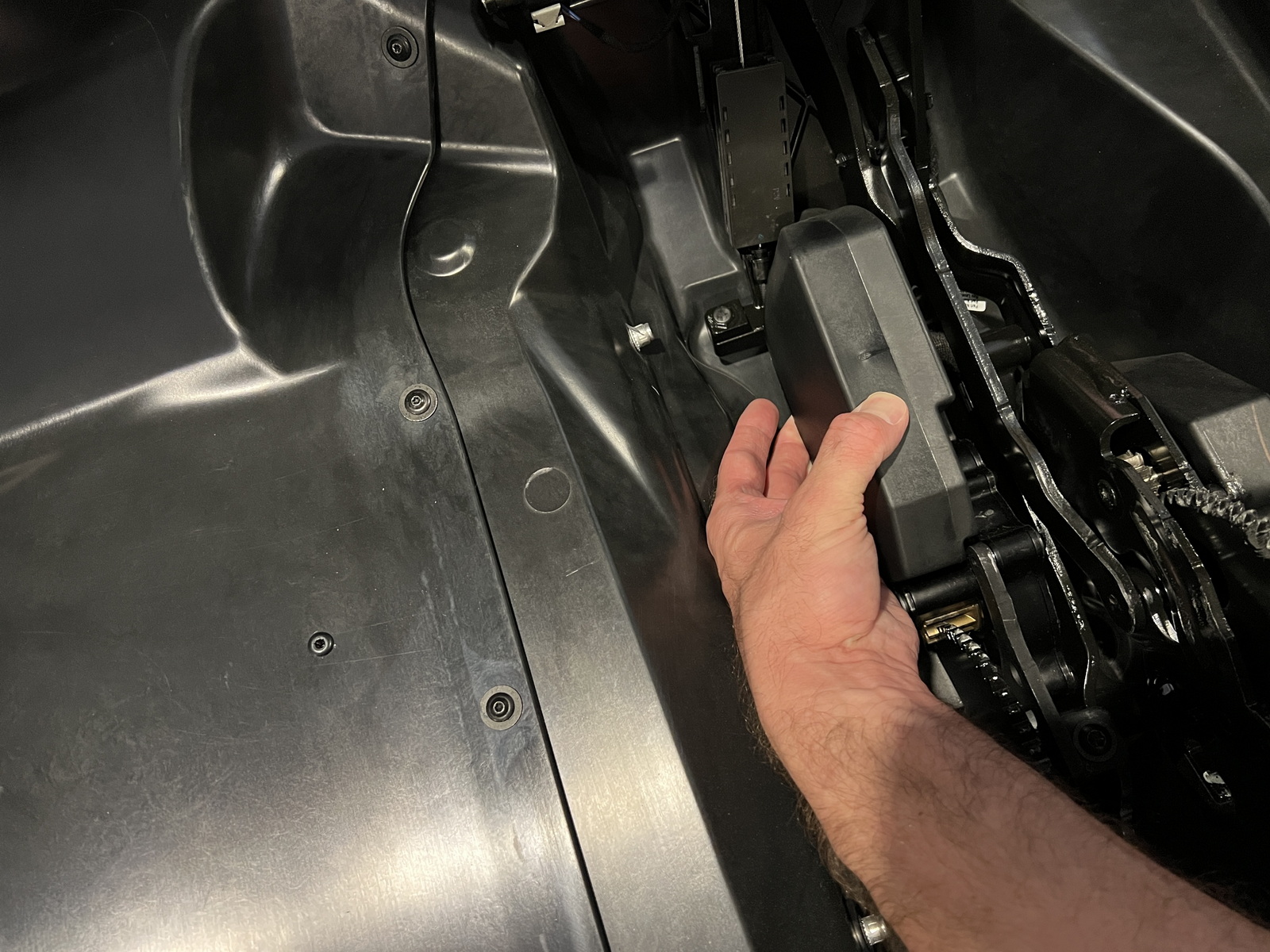
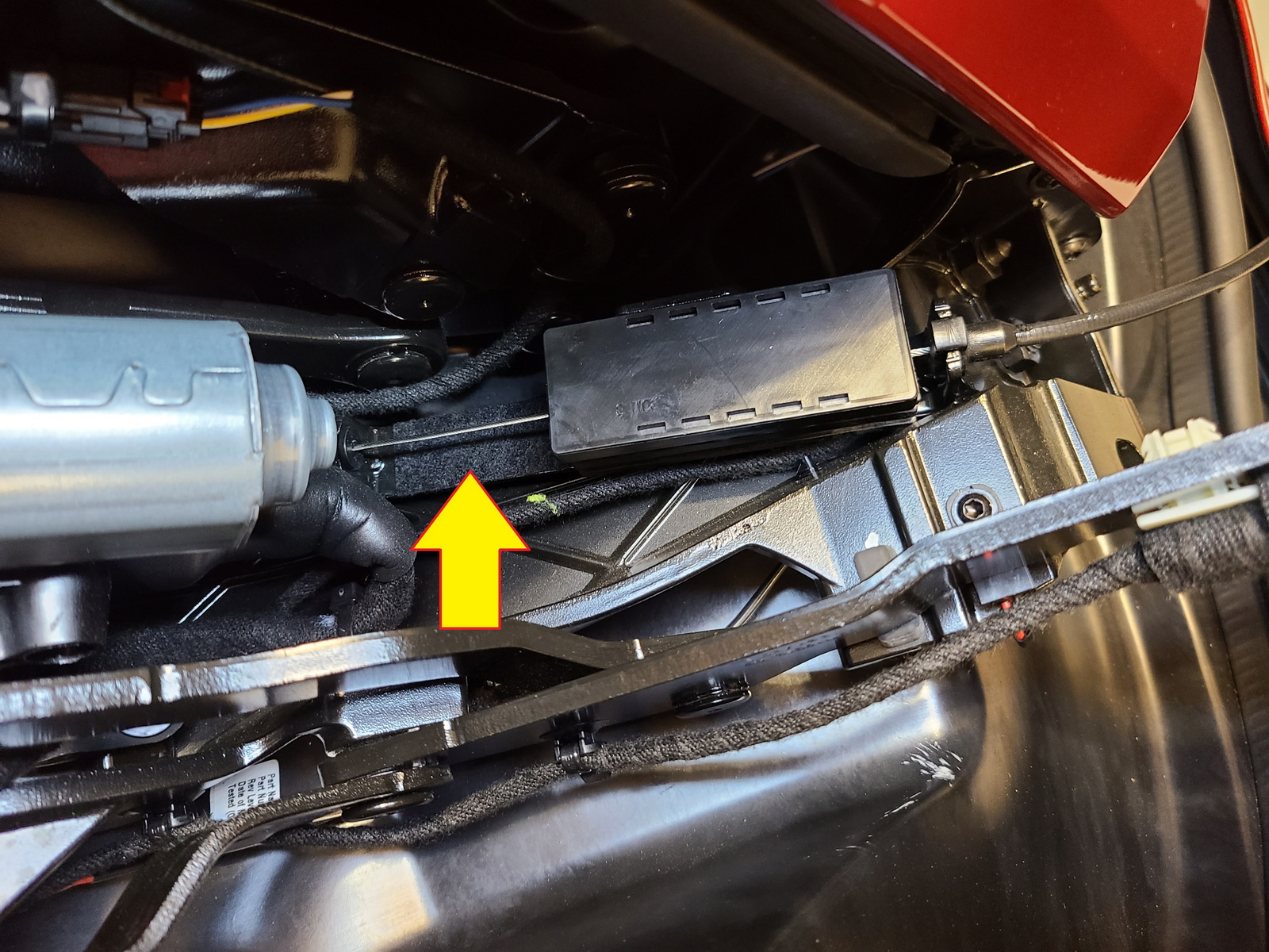
| 5. On the rear end of the drive unit one connector needs to be removed. It is hidden under some foam tape. Peel the foam tape around it off to expose the connector (1). It looks just like the one on the supplied wiring harness. The red tab needs to be pulled out before the locking lever itself can be depressed while wiggling and pulling hard on the plug, just as described in Step 1. DO NOT PULL IT OUT JUST YET. The box with the steel cable (2) is in the way. |
| 6. In order to actually get the plug out of the socket, the roof needs to be moved another small bit and stopped in the position as shown. This will move the black box with the steel cable out of the way just enough. Remember to turn the ignition off before proceeding. |
| Installation - Steps 7-9 | |
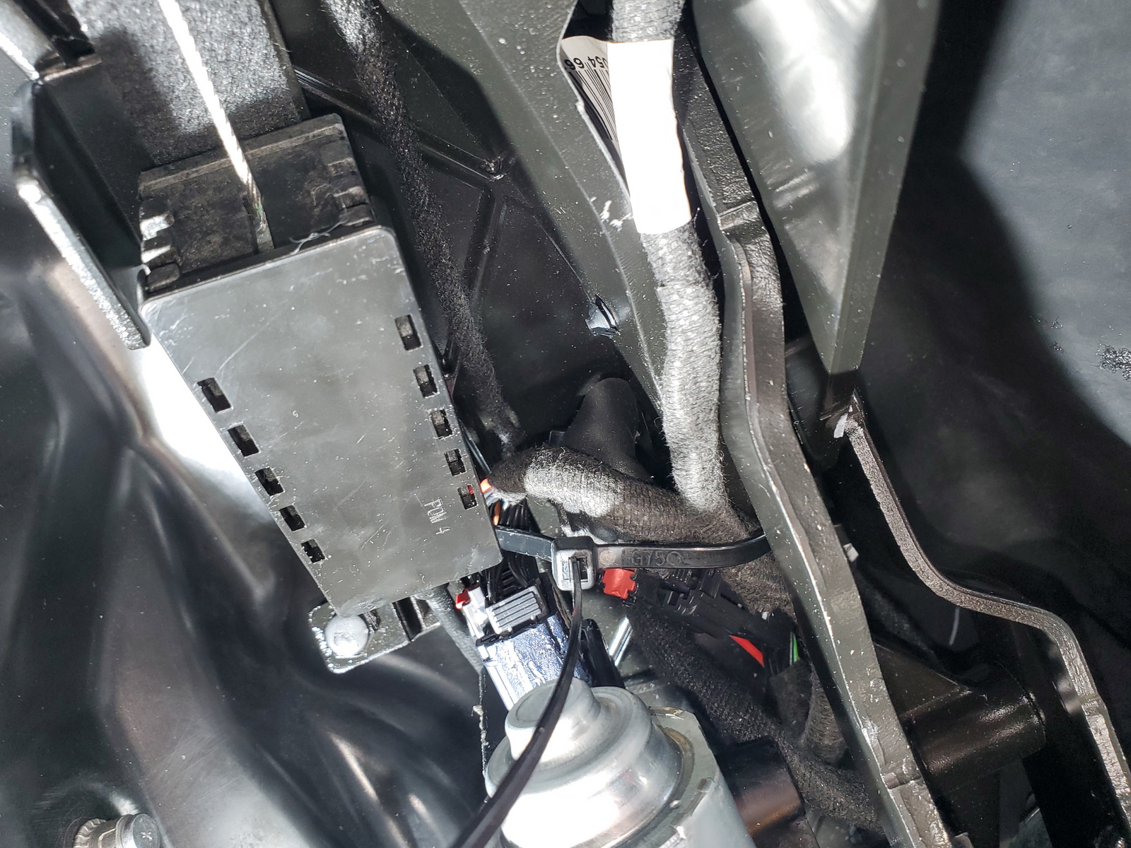
| 7. Here you can see the black box has moved backwards and out of the way. Now there is enough space behind the connector for it to come out of the socket without problems. |
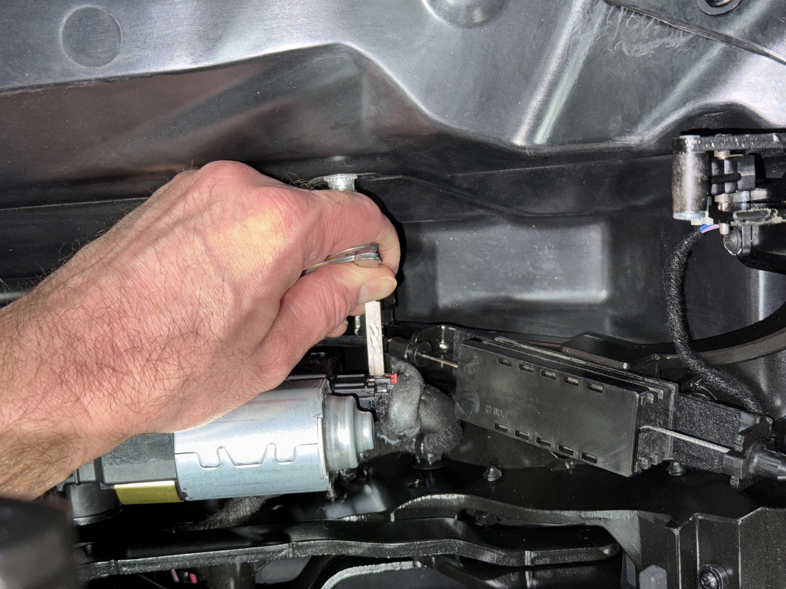
| 8. Using the skills practiced in Step 1, separate the connector from the socket. Pull out the red tab, press on the little black tab, and pull the wire harness out of the motor. The key works very well for this part. Push in with the key blade while wiggling on the plug. You will feel it unlatch and it will come out without excessive force. IMPORTANT: You may have to push the plug in a bit and gently wiggle around in all directions to get the black plastic hook to unlatch and release it. DO NOT USE FORCE OR TOOLS TO PRY IT OUT AS THAT WILL DAMAGE THE CONNECTOR OR SOCKET! |
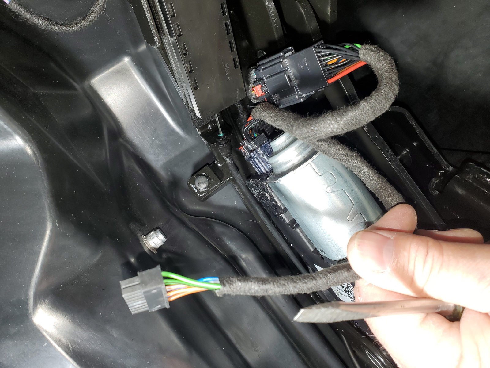
| 9. Connect the plug from the supplied harness to the socket on the drive unit, then connect the original plug to the matching socket on the harness. Press in the red tabs to lock them. |
| Installation - Steps 10-12 | |
| 10. Make sure all connections are tight and that all wiring is safely stowed and tucked away where it can not get jammed in the gear or levers. We recommend using electrical tape or zip ties to secure all wiring in place. |
| 11. Route the module connector under the fixed lever to the space next to the other drive unit where it will not be in the way of any moving parts. Connect the SmartTOP module to the harness. The green LED should light up for 1-2 seconds, then turn off. |
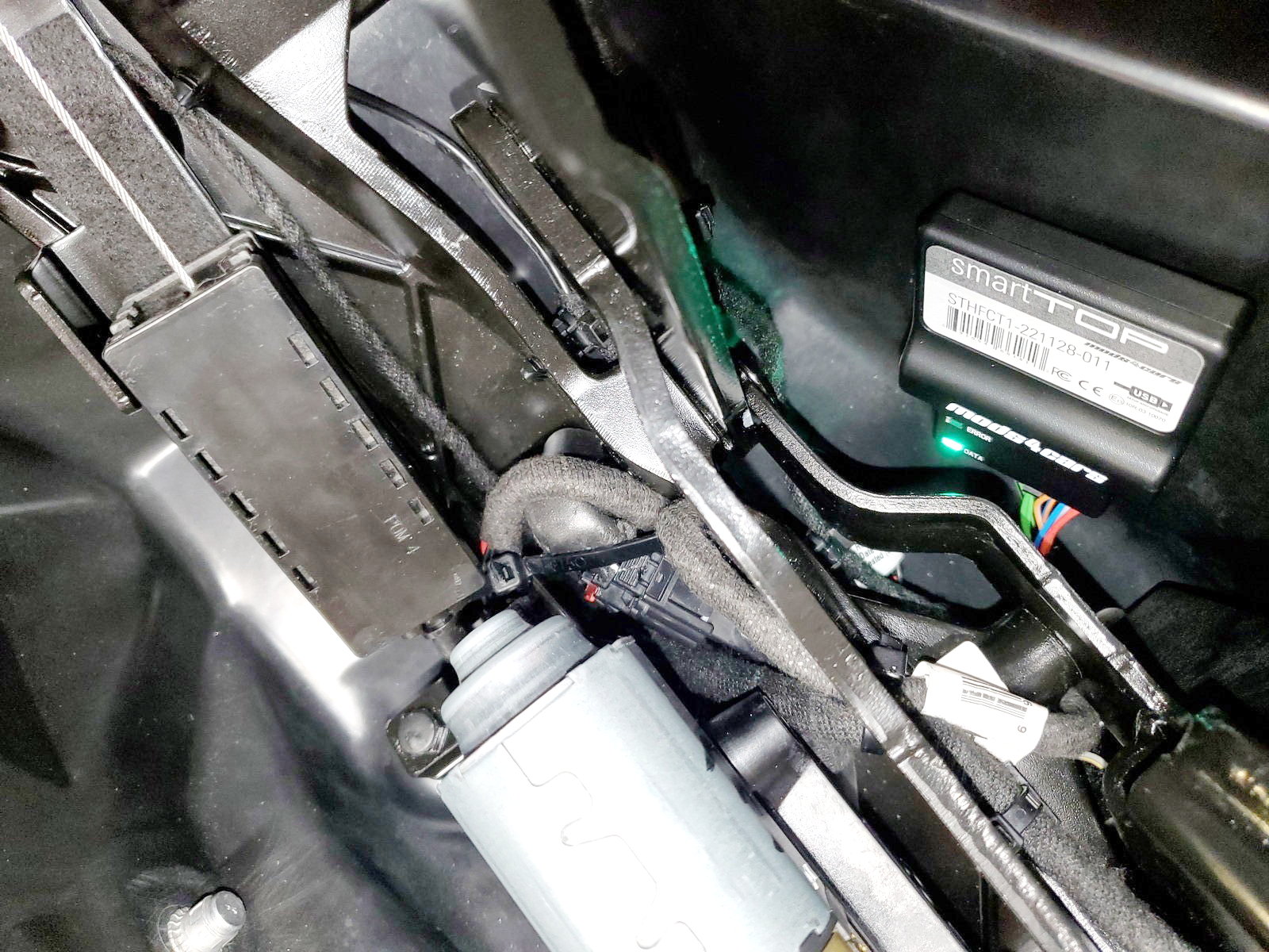
| 12. Tap the unlock button on the remote. The green LED on the module should now flash to indicate a successful installation. Use an alcohol wipe to clean the surface, then attach the module firmly using the supplied velcro sticker. Remember to configure the module using the operation and progamming manual. DO NOT FORGET TO REINSTALL THE PLASTIC COVER FROM STEP 3 OVER THE MOTOR. |