INSTALLATION

STLFVN2
Comfort Roof Control Module for
v1.0
Further information and manuals for all products can be found on our web site
w w w . m o d s 4 c a r s . c o m
PLEASE READ THE COMPLETE MANUAL CAREFULLY BEFORE USING THIS PRODUCT.
INSTALLATION |
|
|
STLFVN2 Comfort Roof Control Module for v1.0 |
Further information and manuals for all products can be found on our web site w w w . m o d s 4 c a r s . c o m |
| We explicitly point out that all functions of this control unit should be used only while exercising caution and responsibility. We can NOT be held liable for any damage or injury caused by installing or using this product. PLEASE READ THE COMPLETE MANUAL CAREFULLY BEFORE USING THIS PRODUCT. |
| Important Information. READ BEFORE INSTALLING! | |
|---|---|
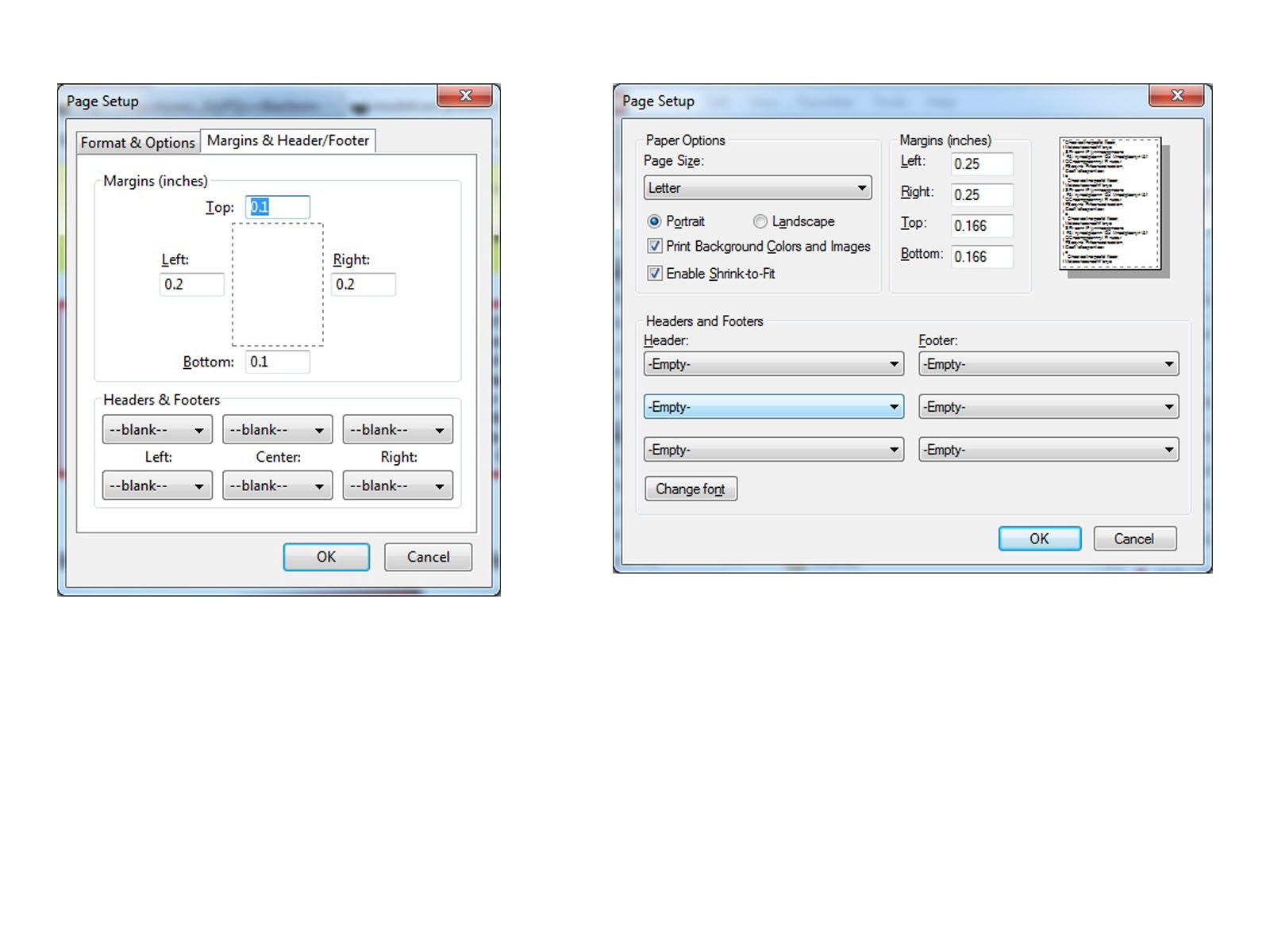
| PRINTING THIS MANUAL This manual is designed to produce completely filled pages. In order to get best print results, simply set the borders to minimum settings in the browser's page setup menu and disable headers and footers. Activate the print preview and if necessary decrease the zoom level until all pages are shown correctly. ALL IMAGES CAN BE CLICKED FOR FULL SIZE in the browser. |

| TROUBLE SHOOTING - NEED TO CONTACT US? If you run into any problems after installing the module, please go over the manual again in great detail, clicking every photo for full size! We now have a full Knowledge Base with Support Ticket system available online at www.mods4cars.com/support If you need to contact us, the best and fastest way to do so is by opening a support ticket there |

| This module comes with our USB Field Upgrade and Configuration Port! We recommend connecting it to a computer BEFORE YOU INSTALL and using our support app "m4cconnect" to do a quick firmware update check. M4cconnect as well as all other information regarding USB update and configuration can be found at www.mods4cars.com/usb. You can even configure and activate your favorite module functions and settings on screen before the module is installed in the car! It is a good idea to permanently install the USB cable with the module in the car, leaving the computer plug in an easily accessible spot for later use with a Wifi/3G/4G connected laptop. |
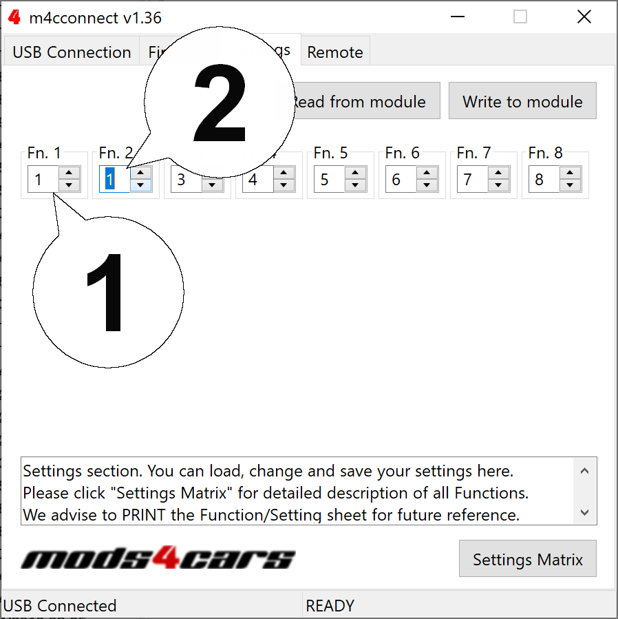
| IMPORTANT TROUBLESHOOTING TIPS If the top does not work properly or at all after installing the module, these tips can be very helpful: 1) Turn Function 1 (Main Switch) off (Setting 0). The module will be completely passive. If the problem still persists and the top won't work, check all connections. Please also check the green DATA LED on the module! 2) Function 2 now has a valet mode (Setting 2) on many modules. Valet mode completely disables opening of the top. Check the setting for function 2 and make sure the module is NOT in valet mode! IMPORTANT: Not all modules have the valet mode! Please check the Operation and Programming Manual! |
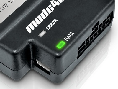
| FUNCTION OF THE DATA LED The DATA LED shows the module status and helps troubleshooting issues during installation: When the ignition is ON: The LED should BLINK (flash) in a regular pattern (about 1x per second). This indicates that the module is receiving data and should work OK. When the ignition is OFF: The LED should BLINK (flash) as long as the data bus is still active and turn off after a while (max 5 min) indicating that the car has entered stand-by (sleep) mode. If the LED is permanently lit with the ignition ON, the module is NOT receiving data from the top controller and all connectors should be checked. If the LED does NOT light up at all when turning the ignition ON, the module is either not getting power or not receiving ANY data. All connectors should be checked. |
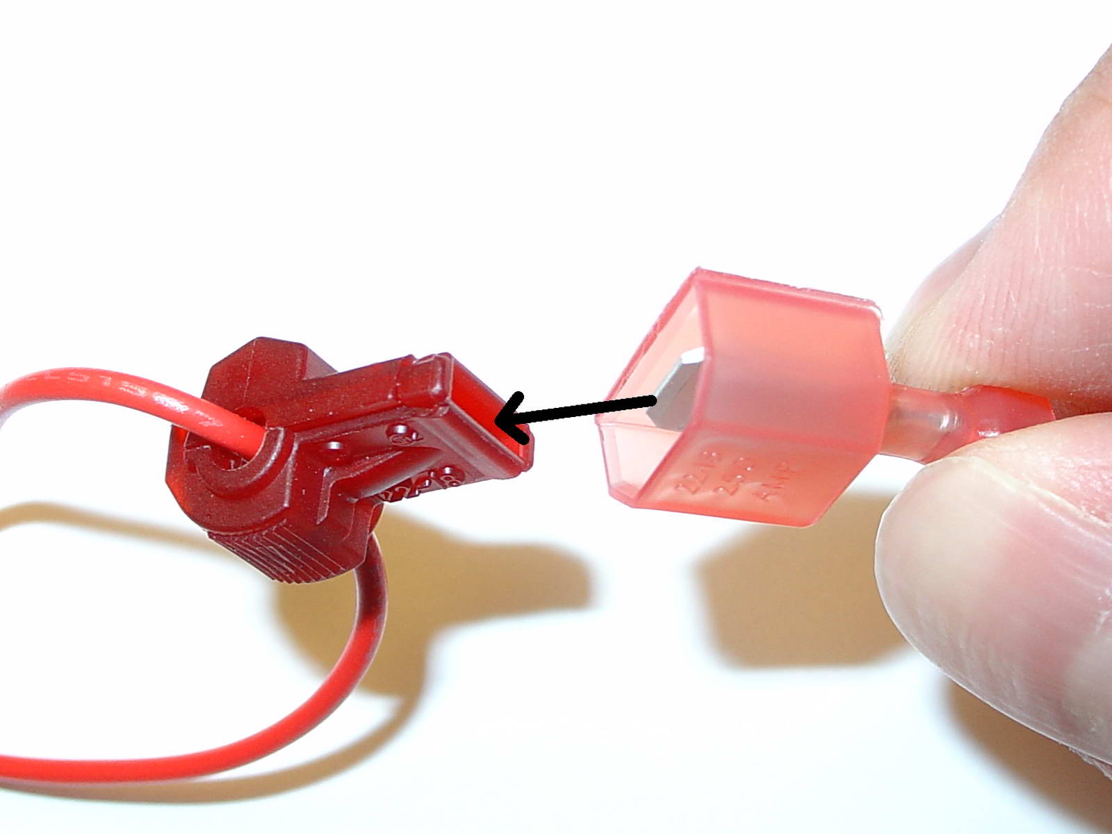
| USE OF THE 3M WIRE TAPS This module is installed using the 3M wire taps very popular with 12V aftermarket industry for their reliability and durability. The most common problem during installation is a bad contact between the plugs from the supply wires and the wire taps. Please make absolutely sure that the metal blades of the plugs slide into the slots of the t-taps. It happens that the blade "misses" the slot and the connection looks correct, but doesn't make electrical contact! The T-taps come in RED (for thin wires), BLUE (for medium wires) and YELLOW (for thick wires). To test if you installed the module correctly after all wires are connected, turn the ignition fully on and watch the green LED on the module. It should blink (flash) to signal a correct installation. If the LED either does not turn on or stays on permanently, there is a bad contact or a missing connection! See detailed explanation of the DATA LED. |
| Installation - Steps 1-3 | |
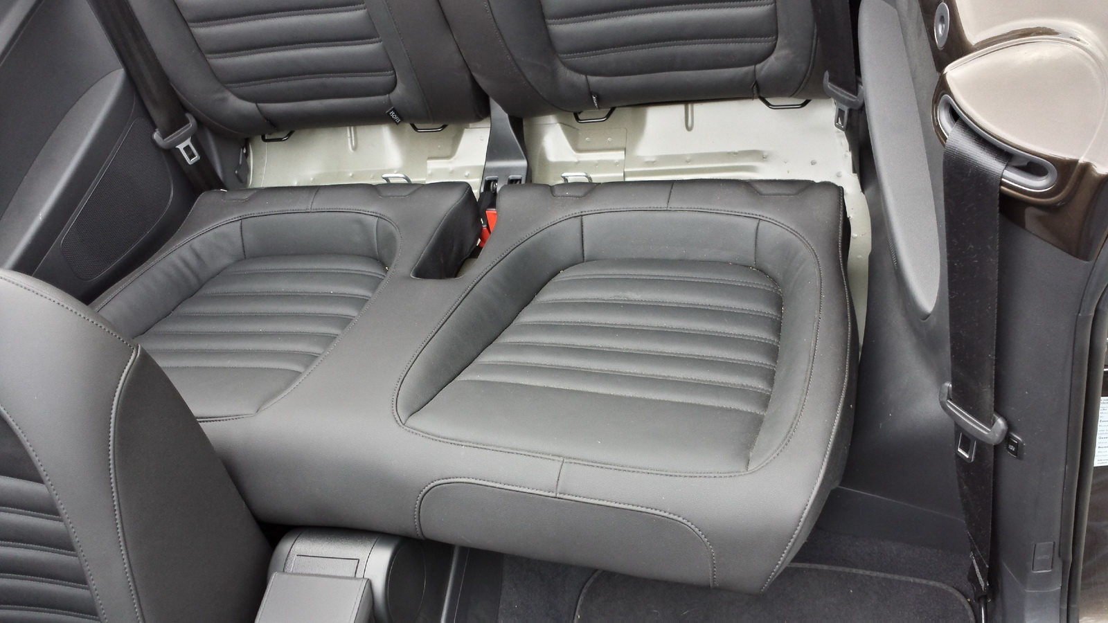
| 1. Remove the rear seat bench by pulling up hard in the front and then sliding it out forward. |
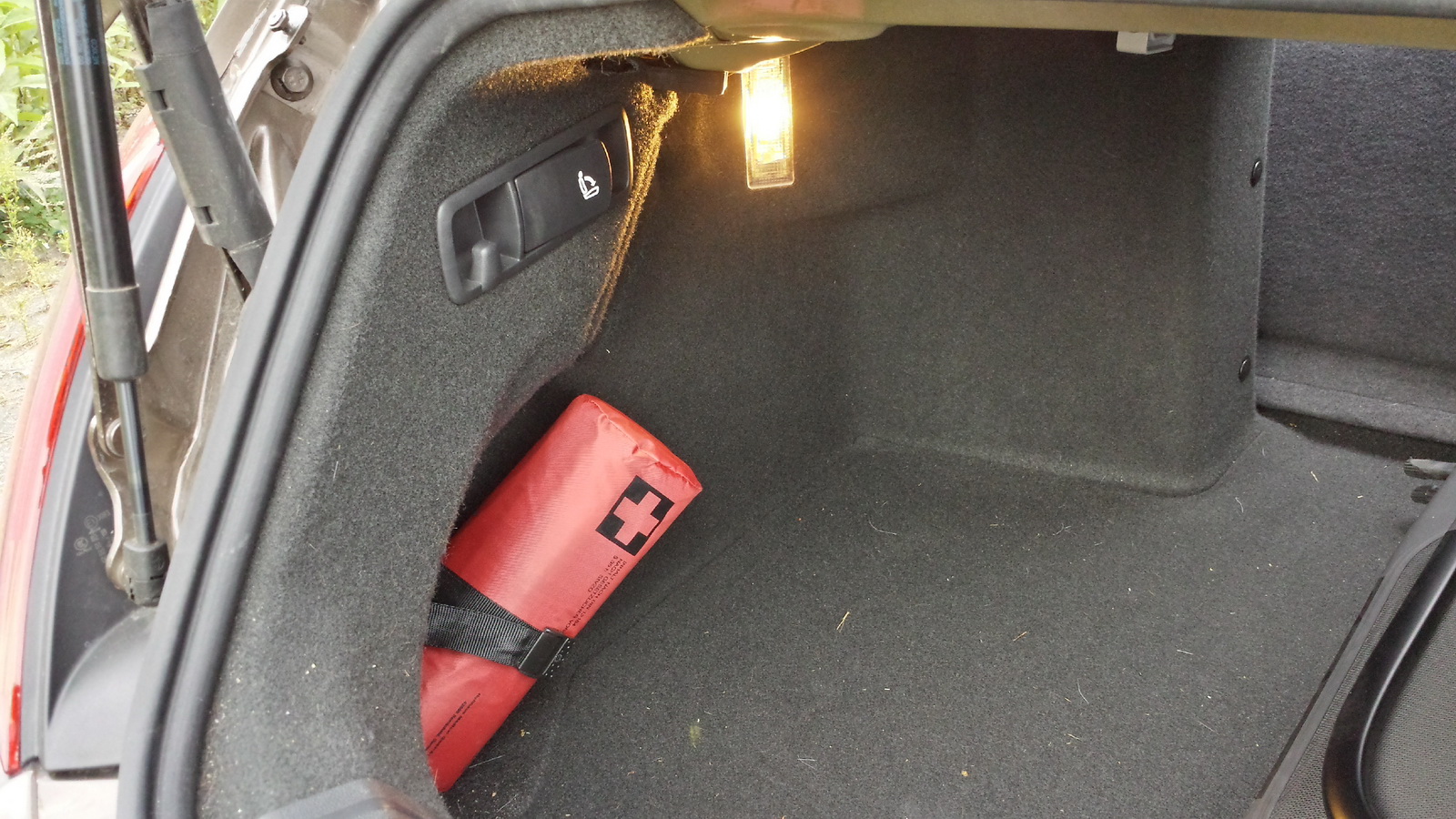
| 2. Flip both rear seats down by pulling on the levers in the trunk. |
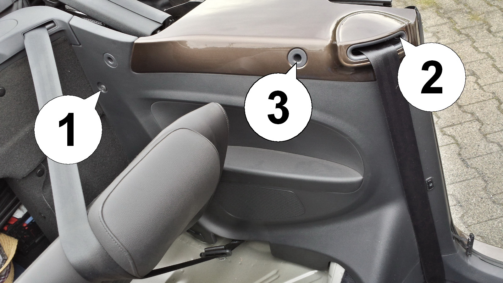
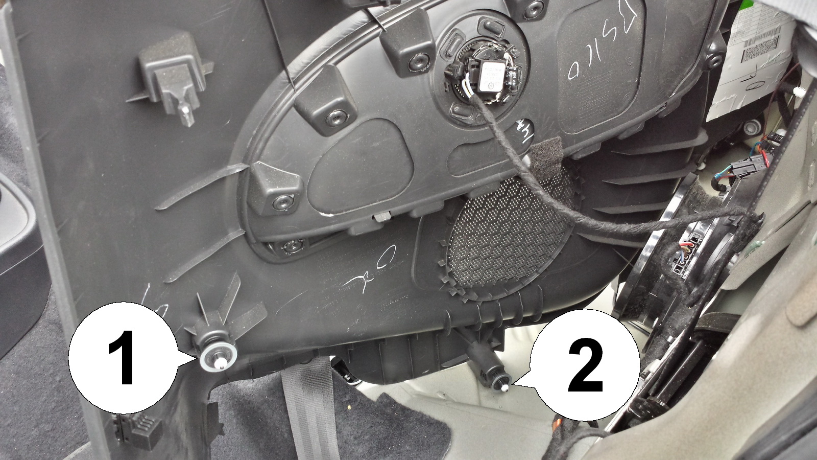
| 3. Remove the marked screws (1) (2) and (3) in order to take the left side panel out. |
| Installation - Steps 4-6 | |
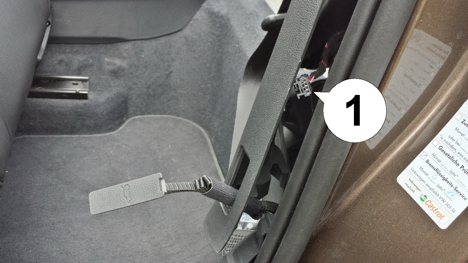
| 4. Lift the side panel up and towards the inside of the car. Some force is needed since it is snapped into place with locking studs (see picture in step 5). Disconnect the small plug (1) carefully and pass the trunk emergency release through the opening sideways. |
| 5. Shown here are the locking studs that keep the panel in place. Make sure they come out of the car chassis and stay attached to the plastic panel. If needed, remove them by hand and attach them as shown. Disconnect the speaker plug. |
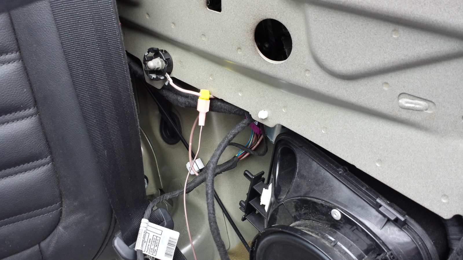
| 6. Attach the supplied wire tap using combination pliers to the thick brown (ground) wire going directly to the chassis grounding bolt close by. Connect the plug from the module wiring harness and make sure it slides all the way in. |
| Installation - Step 7 | |
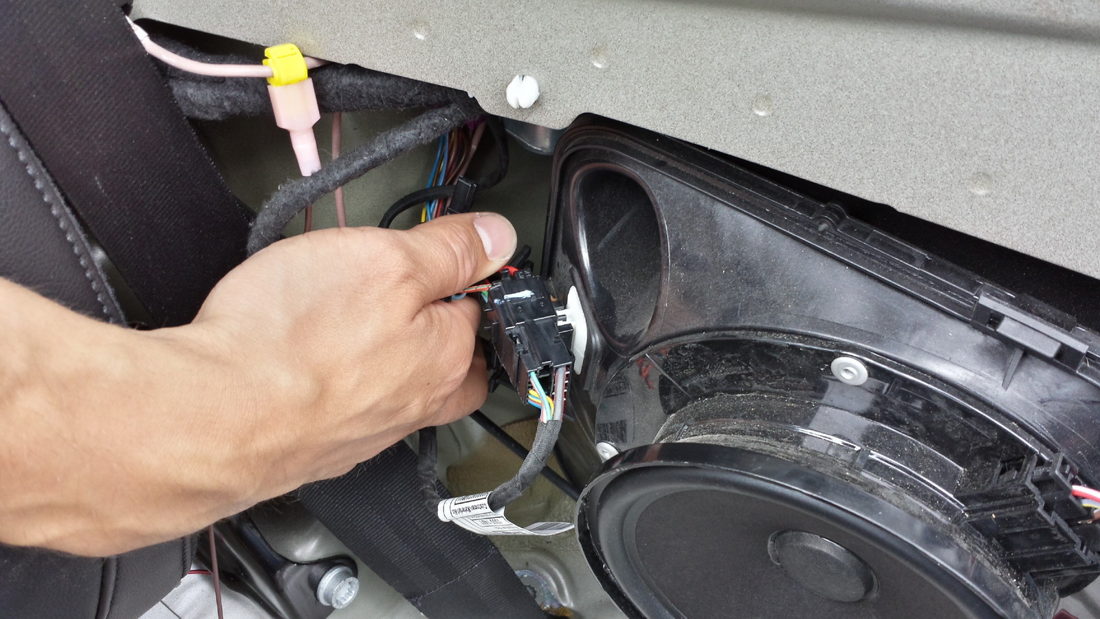
| 7. Disconnect the big black connector and connect the module wiring harness in between, make sure all connections latch securely into place. Connect the module itself to the harness. Test the installation by tapping the unlock button on the remote once. The green DATA LED on the module should now blink to signal a successful installation. Put everything back together in reverse order. |