INSTALLATION with Dual T-HARNESS


STLFVN1

Comfort Roof Control Module for

  • Volkswagen EOS

    v3.xx (Alle Versionen)


  • Further information and manuals for all products can be found on our web site

    w w w . m o d s 4 c a r s . c o m

     
    We explicitly point out that all functions of this control unit should be used only while exercising caution and responsibility. We can NOT be held liable for any damage or injury caused by installing or using this product.
    PLEASE READ THE COMPLETE MANUAL CAREFULLY BEFORE USING THIS PRODUCT.
    Important Information. READ BEFORE INSTALLING!
    PRINTING THIS MANUAL
    This manual is designed to produce completely filled pages. In order to get best print results, simply set the borders to minimum settings in the browser's page setup menu and disable headers and footers.

    Activate the print preview and if necessary decrease the zoom level until all pages are shown correctly.

    ALL IMAGES CAN BE CLICKED FOR FULL SIZE in the browser.
    TROUBLE SHOOTING - NEED TO CONTACT US?
    If you run into any problems after installing the module, please go over the manual again in great detail, clicking every photo for full size!
    We now have a full Knowledge Base with Support Ticket system available online at www.mods4cars.com/support

    If you need to contact us, the best and fastest way to do so is by opening a support ticket there

    This module comes with our USB Field Upgrade and Configuration Port! We recommend connecting it to a computer BEFORE YOU INSTALL and using our support app "m4cconnect" to do a quick firmware update check. M4cconnect as well as all other information regarding USB update and configuration can be found at www.mods4cars.com/usb. You can even configure and activate your favorite module functions and settings on screen before the module is installed in the car! It is a good idea to permanently install the USB cable with the module in the car, leaving the computer plug in an easily accessible spot for later use with a Wifi/3G/4G connected laptop.
    IMPORTANT TROUBLESHOOTING TIPS

    If the top does not work properly or at all after installing the module, these tips can be very helpful:

    • 1) Turn Function 1 (Main Switch) off (Setting 0). The module will be completely passive. If the problem still persists and the top won't work, check all connections. Please also check the green DATA LED on the module!

    • 2) Function 2 now has a valet mode (Setting 2) on many modules. Valet mode completely disables opening of the top. Check the setting for function 2 and make sure the module is NOT in valet mode!

    IMPORTANT: Not all modules have the valet mode! Please check the Operation and Programming Manual!
    FUNCTION OF THE DATA LED

    The DATA LED shows the module status and helps troubleshooting issues during installation:

    • When the ignition is ON: The LED should BLINK (flash) in a regular pattern (about 1x per second). This indicates that the module is receiving data and should work OK.

    • When the ignition is OFF: The LED should BLINK (flash) as long as the data bus is still active and turn off after a while (max 5 min) indicating that the car has entered stand-by (sleep) mode.

    • If the LED is permanently lit with the ignition ON, the module is NOT receiving data from the top controller and all connectors should be checked.

    • If the LED does NOT light up at all when turning the ignition ON, the module is either not getting power or not receiving ANY data. All connectors should be checked.
    Installation - Steps 1-3
    1. First, please make sure that you have the following items:
  • Controller Module
  • Wiring Harness (shown).

    Tools needed:
  • T-20 Torx Screwdriver
  • T-30 Torx Screwdriver
  • Small "Regular" Screwdriver
  • Flashlight (or outside daylight)
  • 2. The installation takes place in the trunk and can be done with the trunk lid in either of the following two positions. Either completely close the roof and open up the trunk lid the regular way or open the roof just to the point where the trunk lid mechanism is tipped all the way back (as shown) in its "service position". The latter method will allow the carpet cover (which you will have to remove during installation) to be accessed a bit more freely.
    The ignition must be turned off and the key removed before continuing with the installation.
    3. Disengage the trunk lid locking hooks, marked with (1) in this and the previous picture, on both sides and lift the trunk lid up carefully.
    Installation - Steps 4-6
    4. The trunk lid can be lifted up as shown, allowing the trunk to be accessed. But mind your head while working in a somewhat ducked position!
    Never operate the roof mechanism with the trunk lid locking hooks disengaged !!!
    5. Remove the luggage divider on the left side by removing the latch (1) at the hinge. Remove divider.
    6. Remove the warning triangle and the floorpanel.
    Installation - Steps 7-9
    7. Behind the warning triangle are two attachment bolts (1&2), which need to be removed. Use the T-20 Torx screwdriver to remove the inner core of the bolts, then pull bolts out. Important: The screwdriver needs to be pushed into the core with force, the opening is actually a regular hex key but we intentionally use a torx to prevent wearing it out while turning the core.
    8. Remove the rubber stripe along the trunk lock, then remove the whole rear plastic cover upwards. Pay attention to the trunk light, which is connected to a set of wires via a removable plug. Push the tabs together to release its locking mechanism while pulling.
    9. Remove the rubber cap on the top of the left carpet cover.
    Installation - Steps 10-12
    10. Remove all attachment bolts of the left carpet cover. It may happen that the whole bolt turns instead of only the core. If that is the case, a second screwdriver can be used to stop the outer part from turning. That way the inner core can easily be removed and the bolt removed.
    11. Remove the left hinge of the divider by removing one T30 Torx screw.
    12. Loosen the whole left carpet cover and pull towards the middle of the trunk and up. Pull out from under the rubber seal and pull away from under the stopper on the upper left. Make sure all attachment bolts have been removed.
    ATTENTION: Lift up the carpet cover VERY SLOWLY and locate the wires running to the luggage divider switch (see next two steps).
    Installation - Steps 13-15
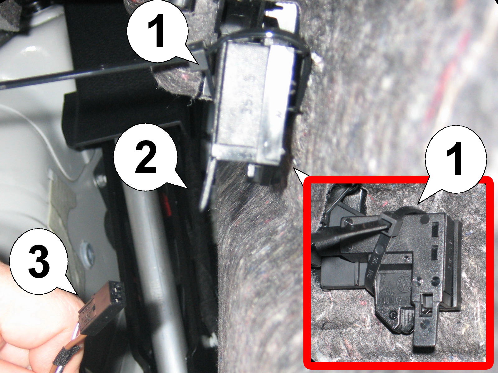
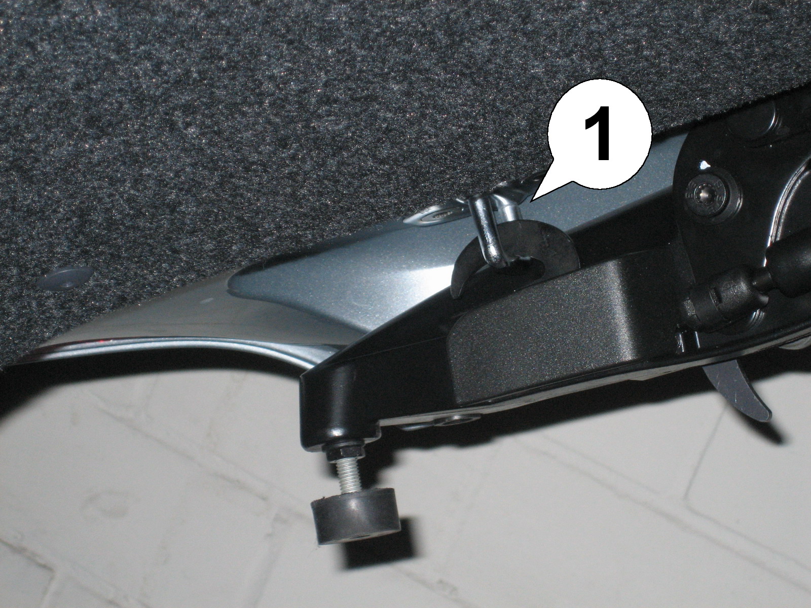
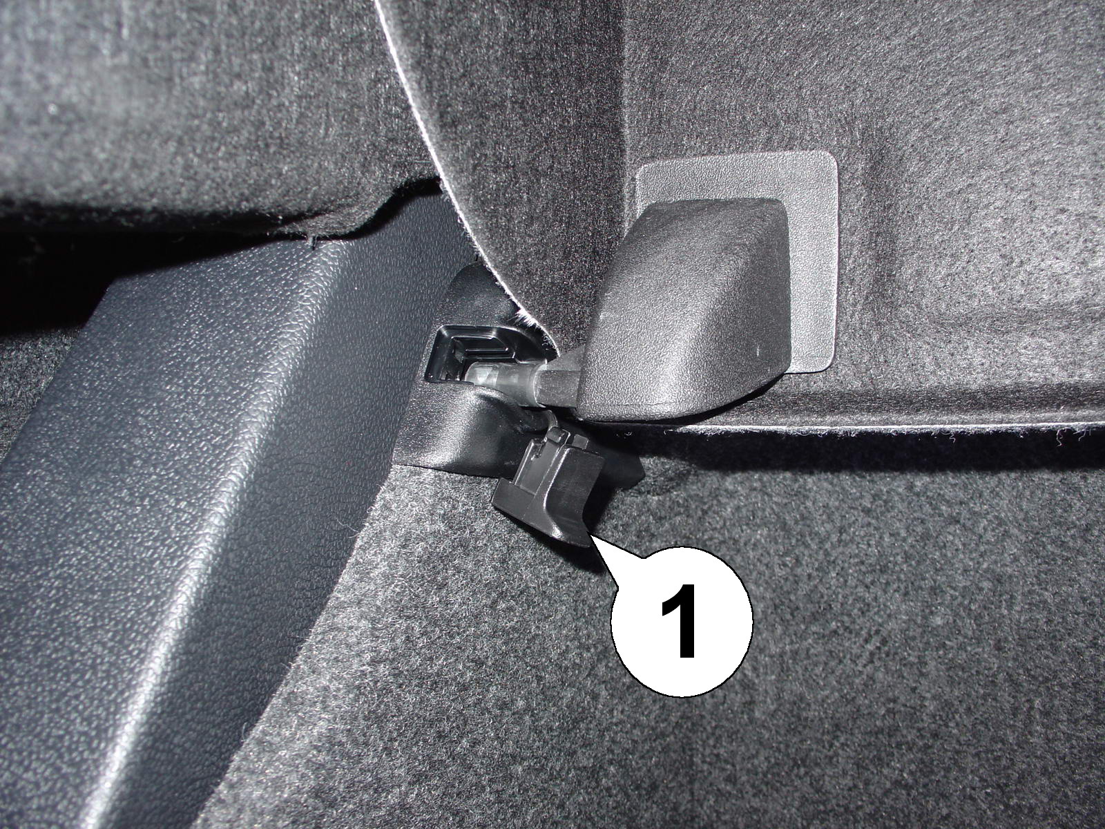
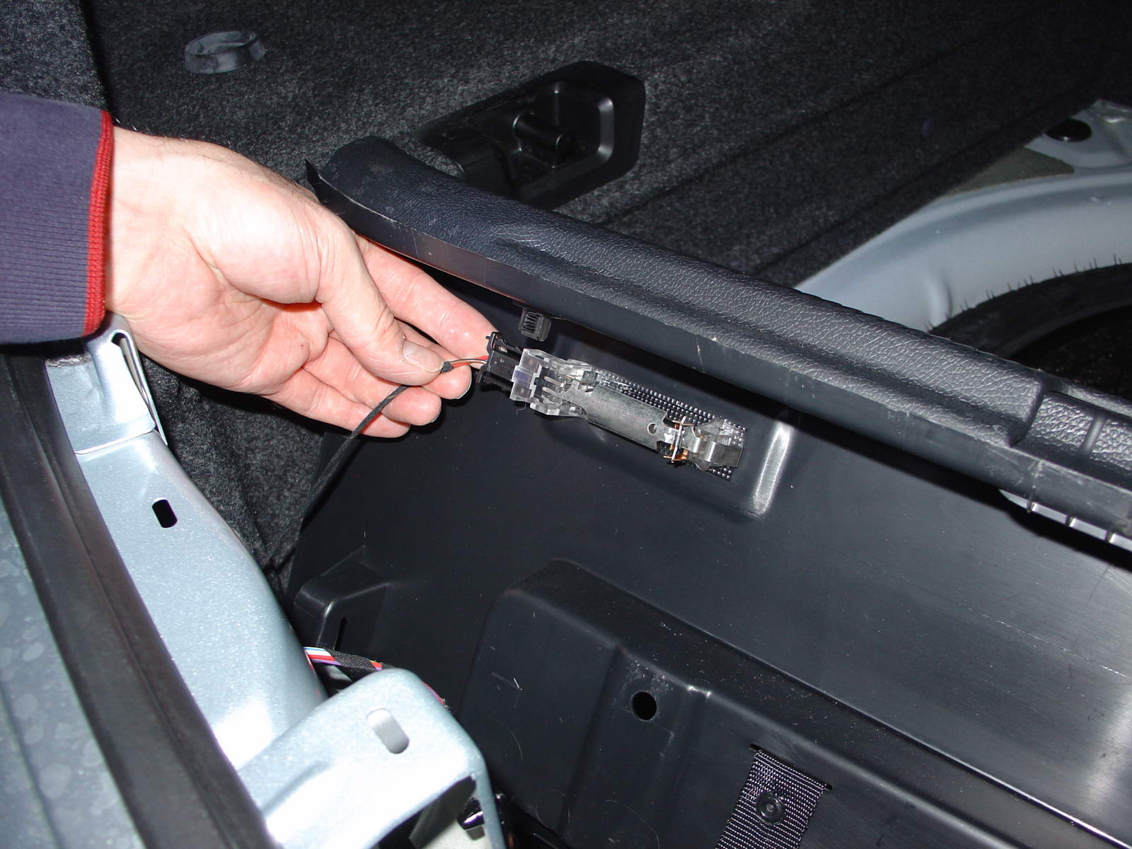
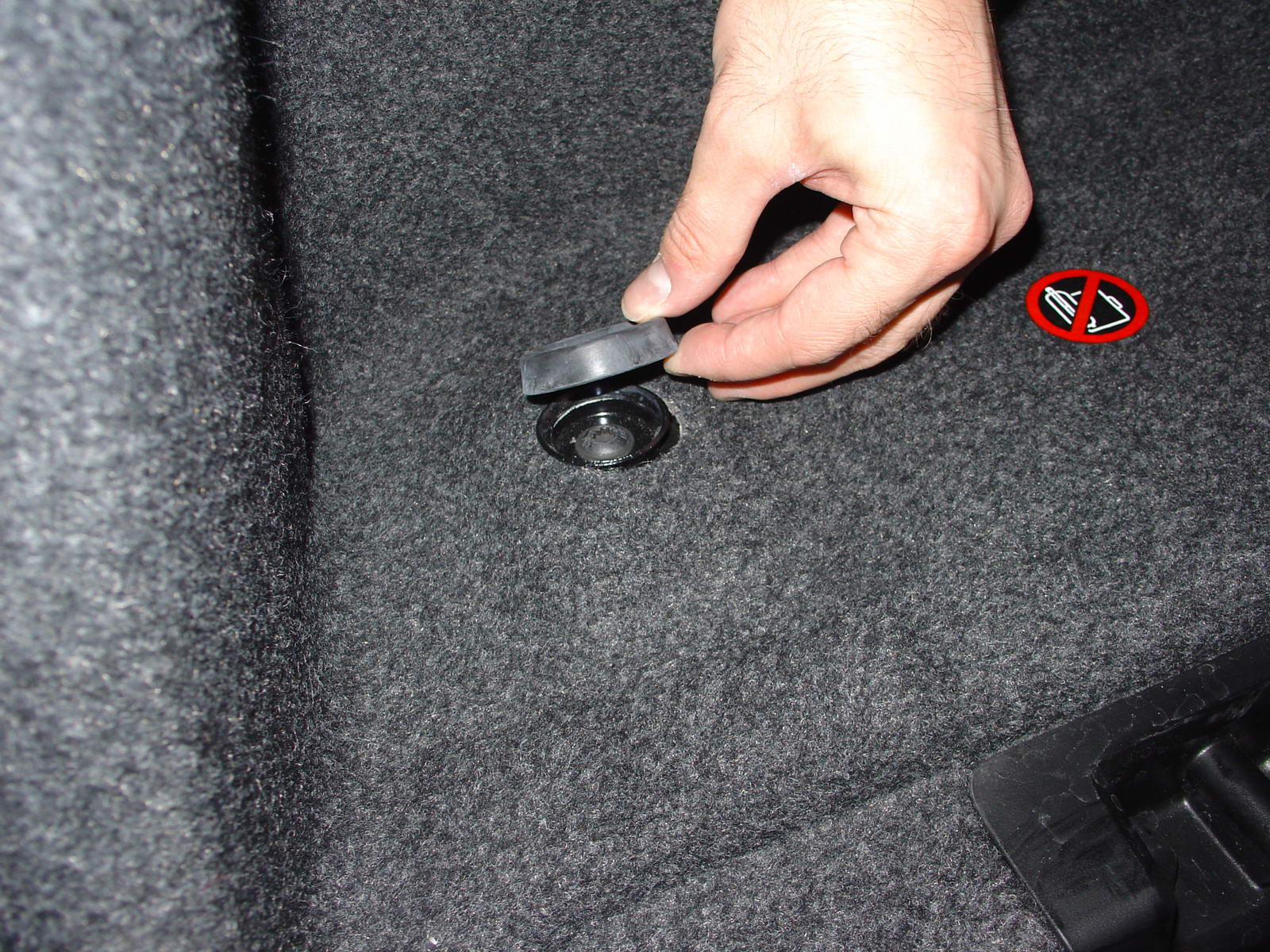
    13. Carefully lift the carpet cover up and unclip the divider switch (1). It is mounted directly under the plastic mechanism where the divider usually locks into place. IMPORTANT: On some EOS models the luggage divider switch (1) is secured into place with a cable tie. If that is the case, unplug its connector (3) by pushing the tab (2) outward while pulling down on the connector. Leave the switch itself in place.
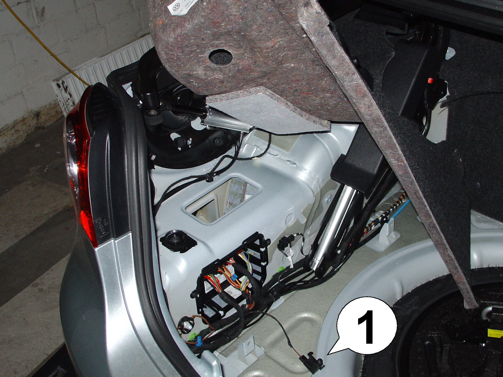
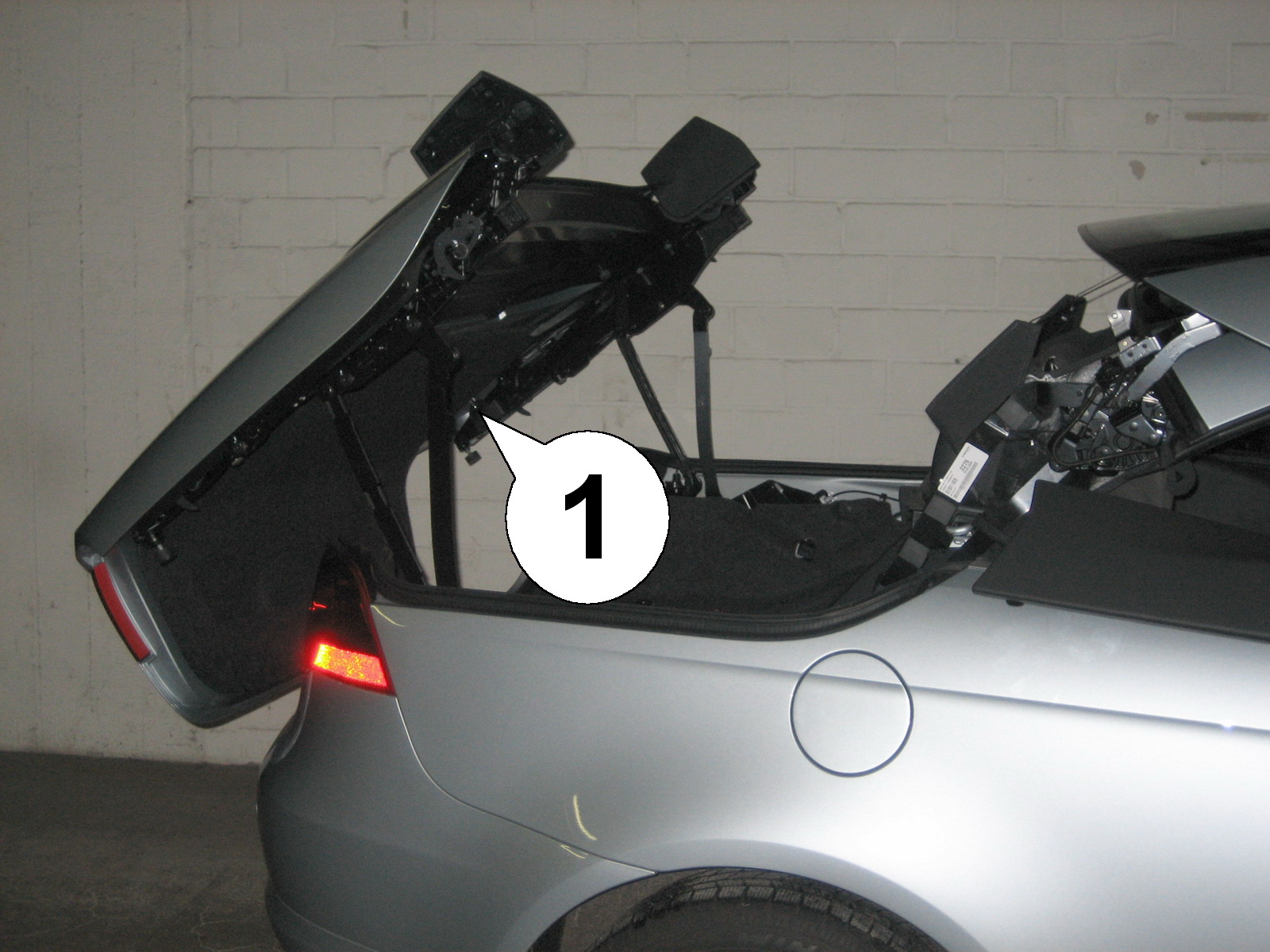
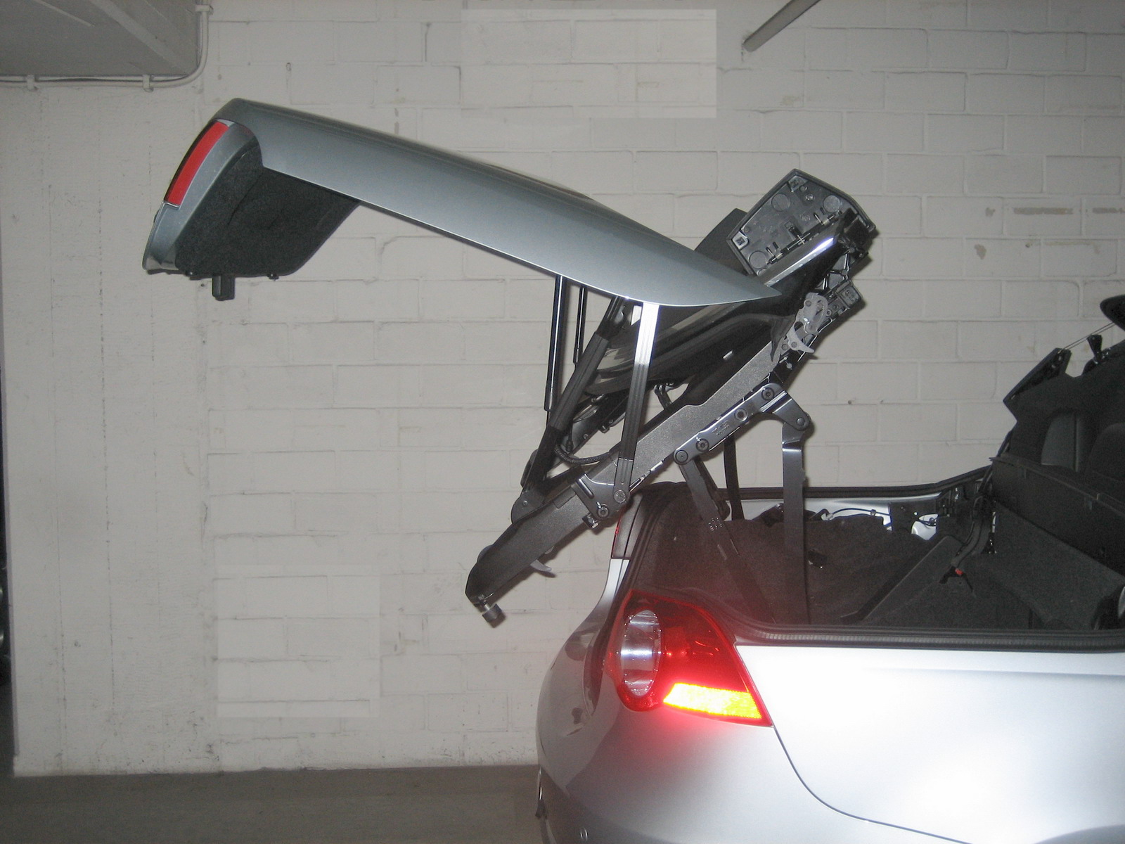
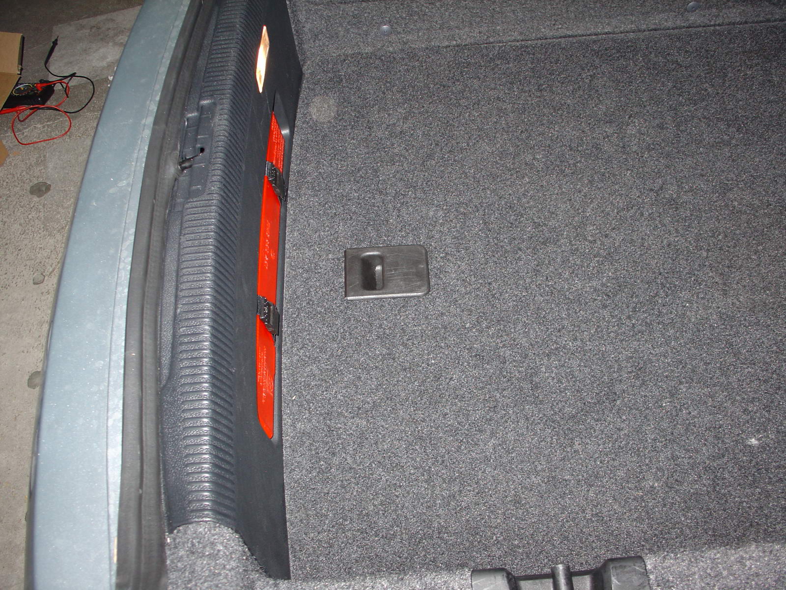
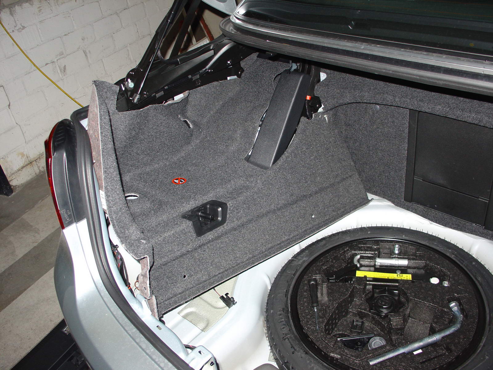
    14. Twist the whole cover counterclockwise while lifting it up. Then place the rear corner onto the spare wheel or styrofoam cover, to make the cover stay up as shown. The luggage divider switch is marked in the picture with (1).
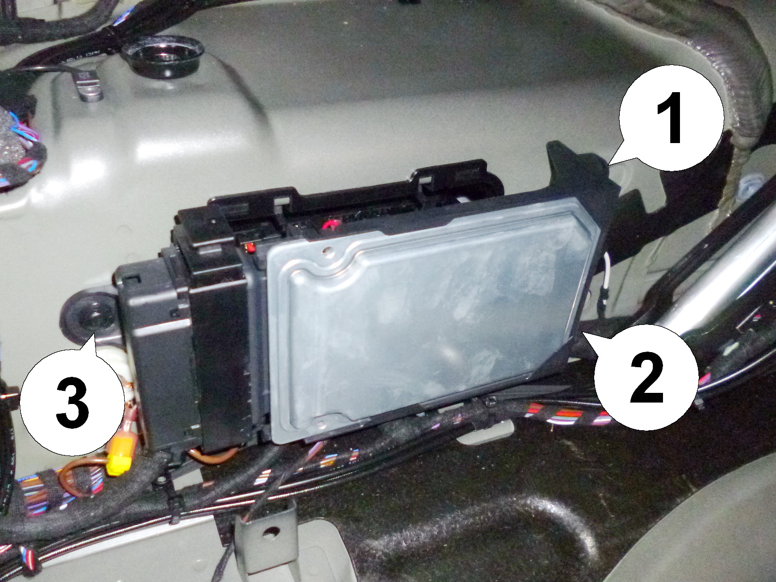
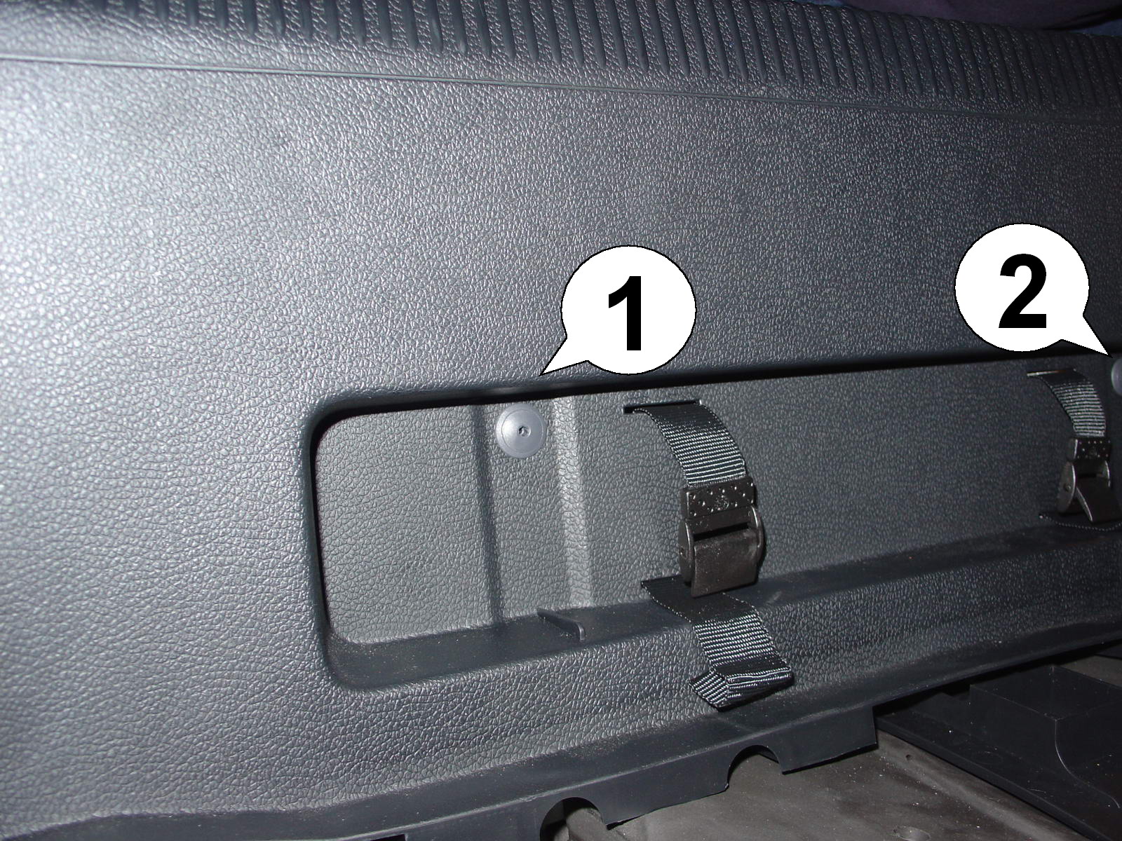
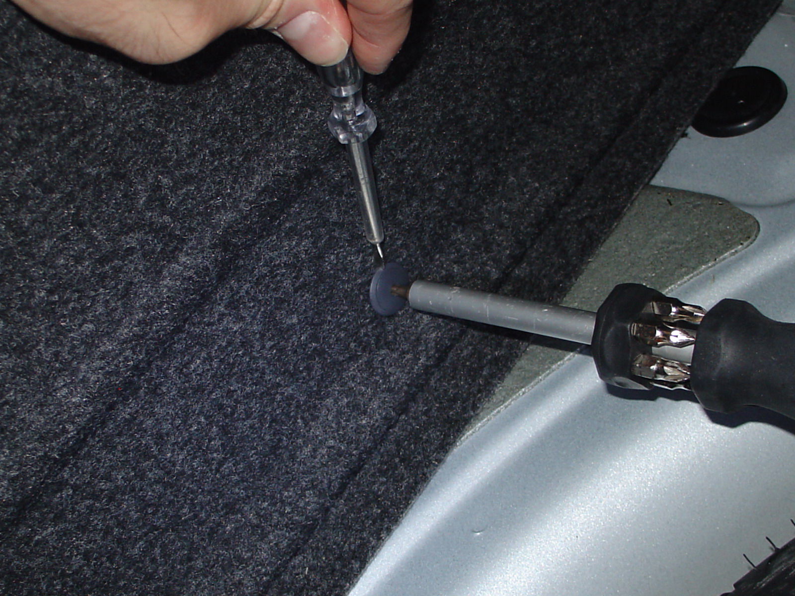
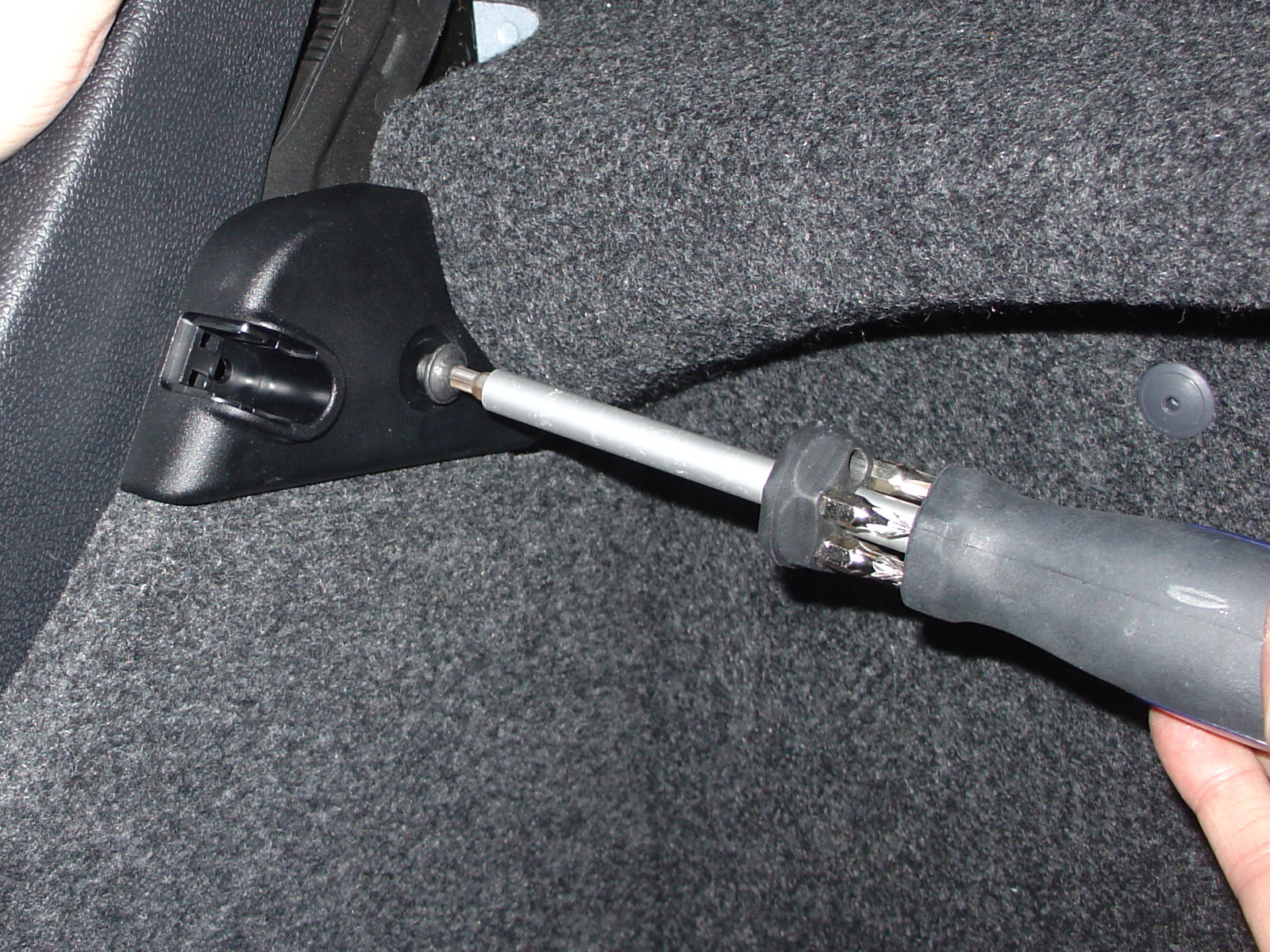
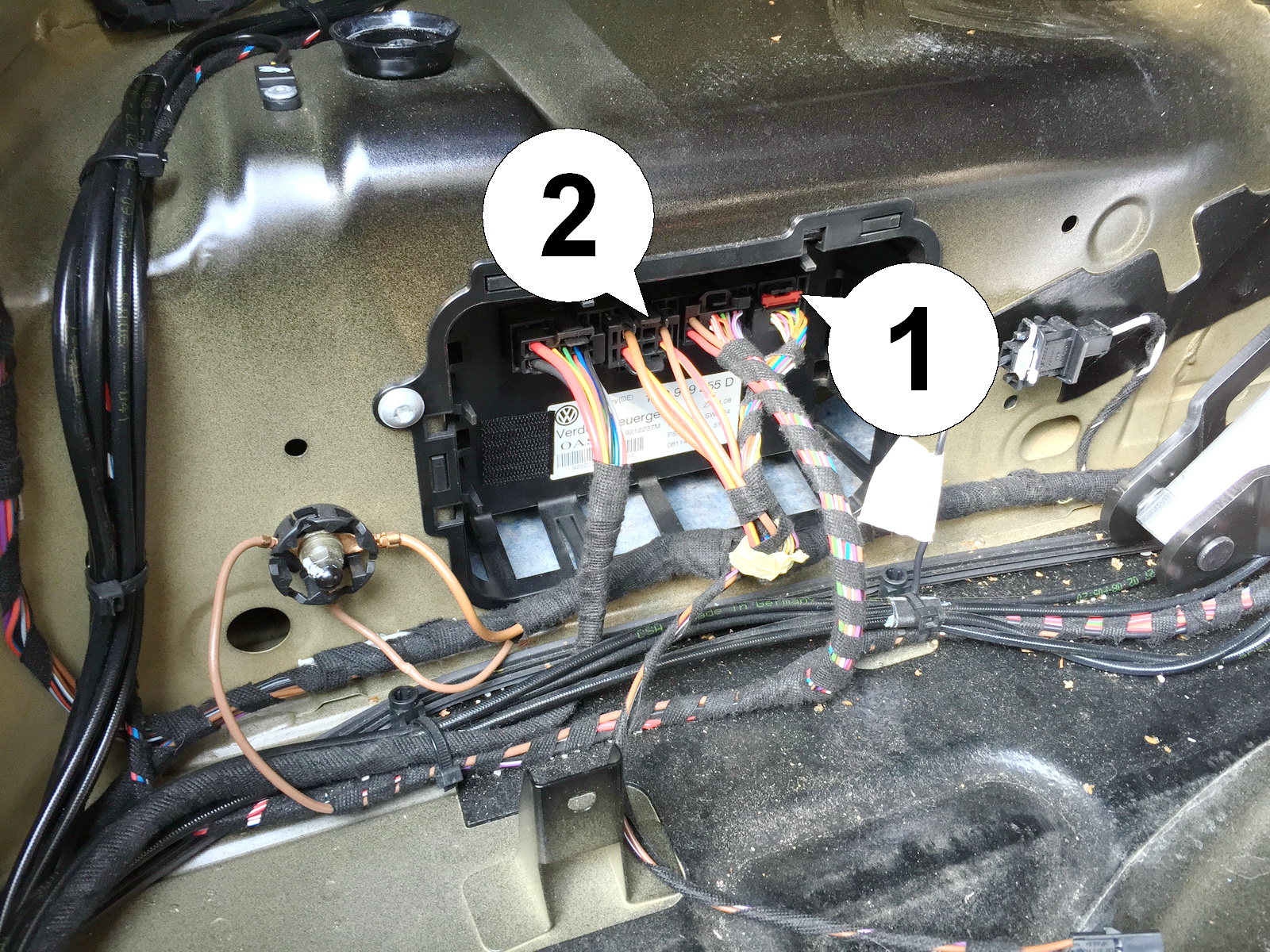
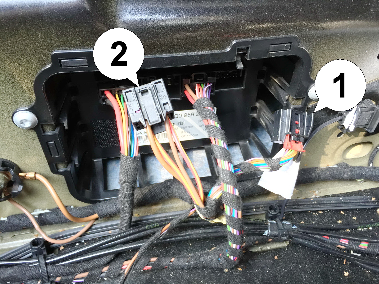
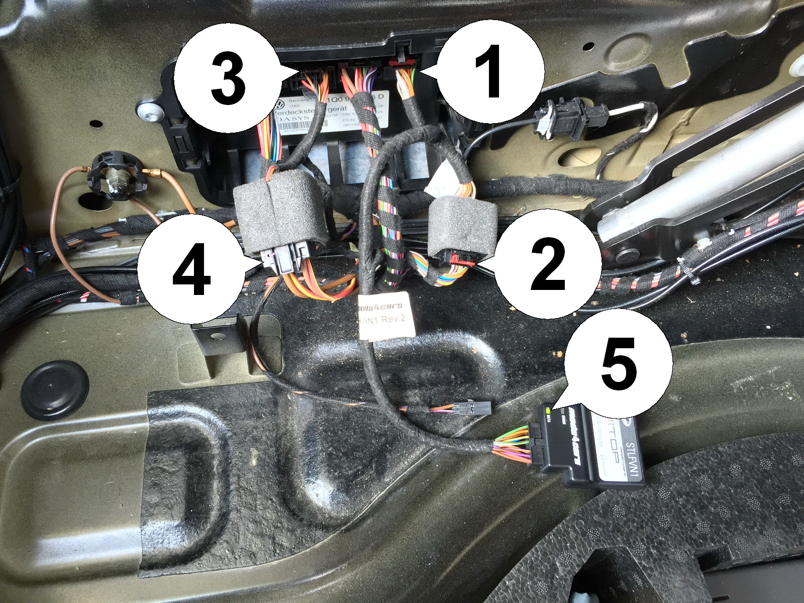
    15. If the top controller is not accessible as shown in step 14 (on cars with DCC suspension there is another control unit mounted in front of it), simply remove the pegs out of the attachment bolts (1,2,3) and remove the entire bracket with the DCC unit, until you can get to the top controller as shown in the next step.
    Installation - Steps 16-18
    16. Convertible top control module exposed. Remove the following plugs. The data plug on the far right (1). Pull the red bracket out, then push the black tab down while pulling the plug out. If needed, look at the same plug on the module harness as a reference. Then remove the power plug (2) which is the second plug from the left. Also here push the black tab down while pulling the plug out.
    17. Shown in this picture: Both plugs removed. Data plug (1) and power plug (2). Both need to be replaced now at the top controller by the same ones from the module harness and then these need to be connected to the matching sockets on the harness.
    18. Connect the harness data plug (1) to the top controller, connect the original data plug (2) to the socket. Then connect the harness power plug (3) to the top controller and connect the original power plug (4) to the matching socket on the harness. Make sure all plugs latch securely into place. Push the red locking brackets in. Connect the module. Now tap the unlock button on the remote once and check the green DATA LED on the module. It should blink and thereby signal a successful install. Stow the module in the void between all the wires right in front of the top controller. Secure it with the supplied velcro sticker. Don't forget to reconnect the luggage divider switch when reassembling everything! We recommend leaving the USB cable accessible for later firmware updates or configuration via laptop.