INSTALLATION
STHFNN1
Comfort Roof Control Module for
v1.0
Further information and manuals for all products can be found on our web site
w w w . m o d s 4 c a r s . c o m
PLEASE READ THE COMPLETE MANUAL CAREFULLY BEFORE USING THIS PRODUCT.
INSTALLATION |
|
|
STHFNN1 Comfort Roof Control Module for v1.0 |
Further information and manuals for all products can be found on our web site w w w . m o d s 4 c a r s . c o m |
| We explicitly point out that all functions of this control unit should be used only while exercising caution and responsibility. We can NOT be held liable for any damage or injury caused by installing or using this product. PLEASE READ THE COMPLETE MANUAL CAREFULLY BEFORE USING THIS PRODUCT. |
| Important Information. READ BEFORE INSTALLING! | |
|---|---|
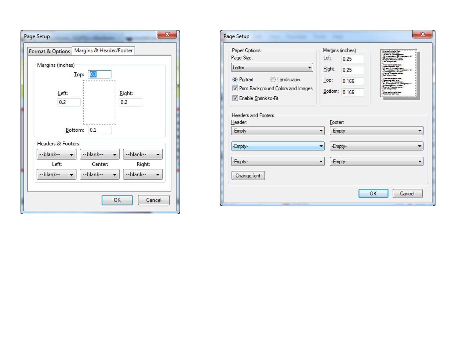
| PRINTING THIS MANUAL This manual is designed to produce completely filled pages. In order to get best print results, simply set the borders to minimum settings in the browser's page setup menu and disable headers and footers. Activate the print preview and if necessary decrease the zoom level until all pages are shown correctly. ALL IMAGES CAN BE CLICKED FOR FULL SIZE in the browser. |

| TROUBLE SHOOTING - NEED TO CONTACT US? If you run into any problems after installing the module, please go over the manual again in great detail, clicking every photo for full size! We now have a full Knowledge Base with Support Ticket system available online at www.mods4cars.com/support If you need to contact us, the best and fastest way to do so is by opening a support ticket there |
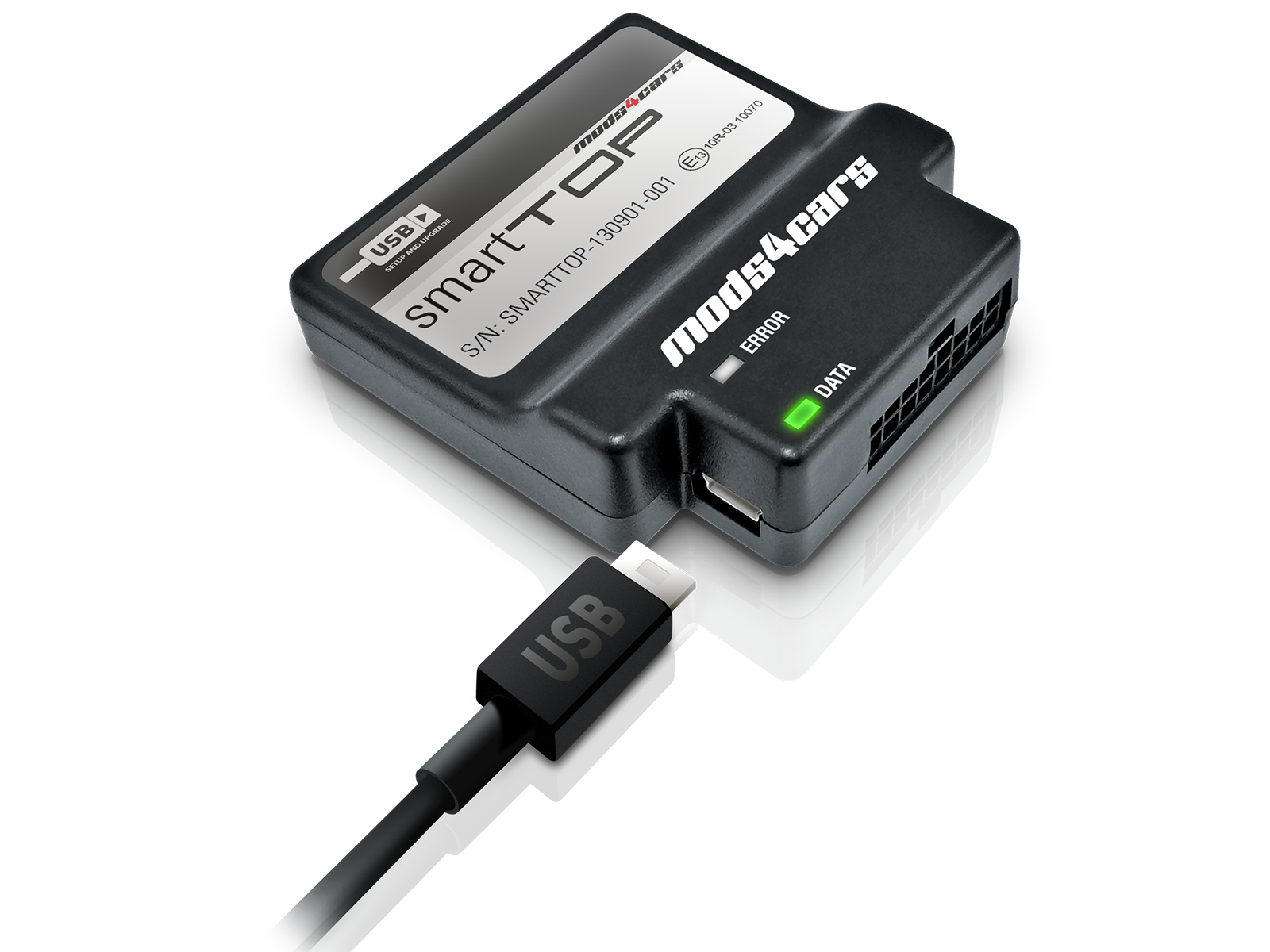
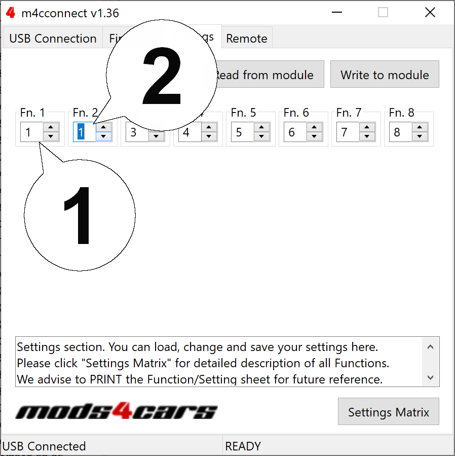
| This module comes with our USB Field Upgrade and Configuration Port! We recommend connecting it to a computer BEFORE YOU INSTALL and using our support app "m4cconnect" to do a quick firmware update check. M4cconnect as well as all other information regarding USB update and configuration can be found at www.mods4cars.com/usb. You can even configure and activate your favorite module functions and settings on screen before the module is installed in the car! It is a good idea to permanently install the USB cable with the module in the car, leaving the computer plug in an easily accessible spot for later use with a Wifi/3G/4G connected laptop. |
| IMPORTANT TROUBLESHOOTING TIPS If the top does not work properly or at all after installing the module, these tips can be very helpful: 1) Turn Function 1 (Main Switch) off (Setting 0). The module will be completely passive. If the problem still persists and the top won't work, check all connections. Please also check the green DATA LED on the module! 2) Function 2 now has a valet mode (Setting 2) on many modules. Valet mode completely disables opening of the top. Check the setting for function 2 and make sure the module is NOT in valet mode! IMPORTANT: Not all modules have the valet mode! Please check the Operation and Programming Manual! |
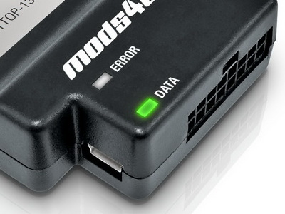
| FUNCTION OF THE DATA LED The DATA LED shows the module status and helps troubleshooting issues during installation: When the ignition is ON: The LED should BLINK (flash) in a regular pattern (about 1x per second). This indicates that the module is receiving data and should work OK. When the ignition is OFF: The LED should BLINK (flash) as long as the data bus is still active and turn off after a while (max 5 min) indicating that the car has entered stand-by (sleep) mode. If the LED is permanently lit with the ignition ON, the module is NOT receiving data from the top controller and all connectors should be checked. If the LED does NOT light up at all when turning the ignition ON, the module is either not getting power or not receiving ANY data. All connectors should be checked. |
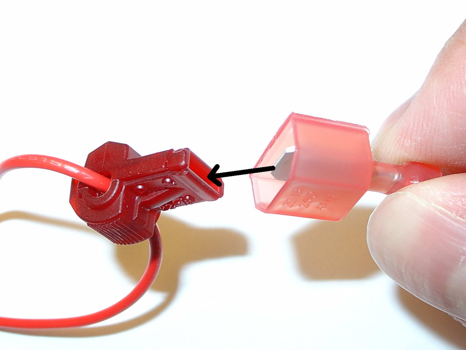
| USE OF THE 3M WIRE TAPS This module is installed using the 3M wire taps very popular with 12V aftermarket industry for their reliability and durability. The most common problem during installation is a bad contact between the plugs from the supply wires and the wire taps. Please make absolutely sure that the metal blades of the plugs slide into the slots of the t-taps. It happens that the blade "misses" the slot and the connection looks correct, but doesn't make electrical contact! The T-taps come in RED (for thin wires), BLUE (for medium wires) and YELLOW (for thick wires). To test if you installed the module correctly after all wires are connected, turn the ignition fully on and watch the green LED on the module. It should blink (flash) to signal a correct installation. If the LED either does not turn on or stays on permanently, there is a bad contact or a missing connection! See detailed explanation of the DATA LED. |
| Installation - Steps 1-3 | |
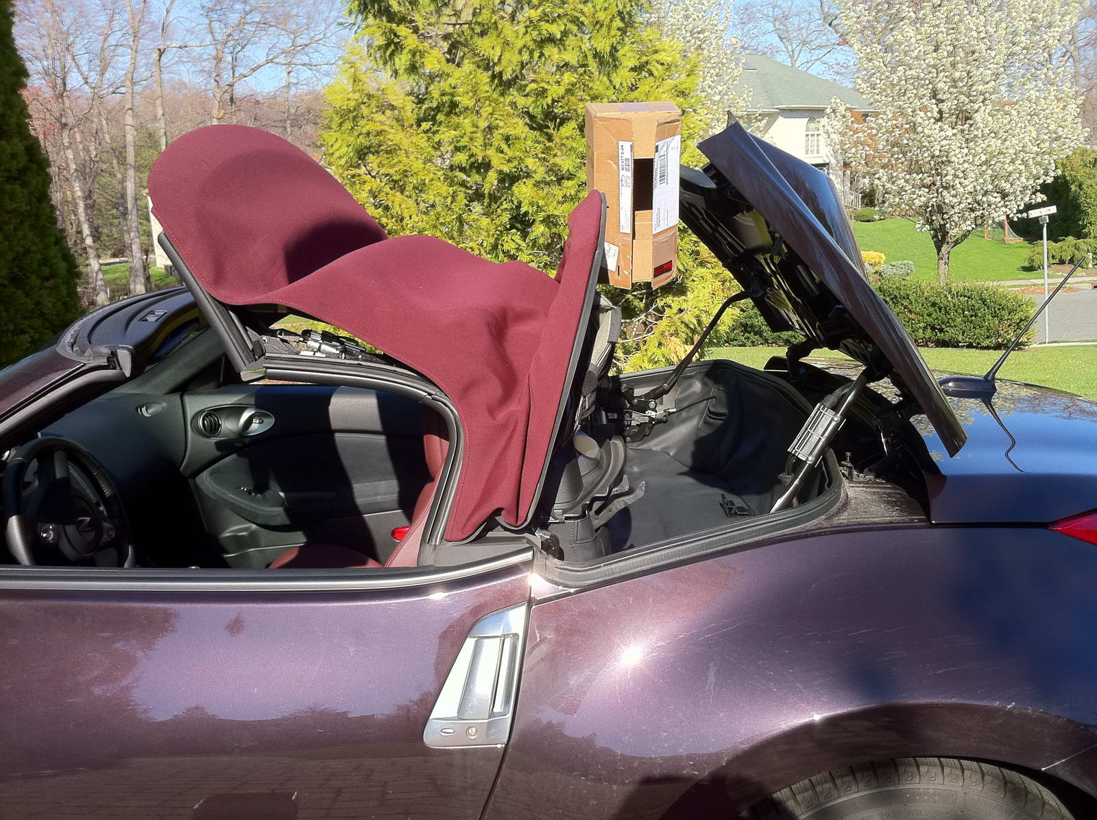
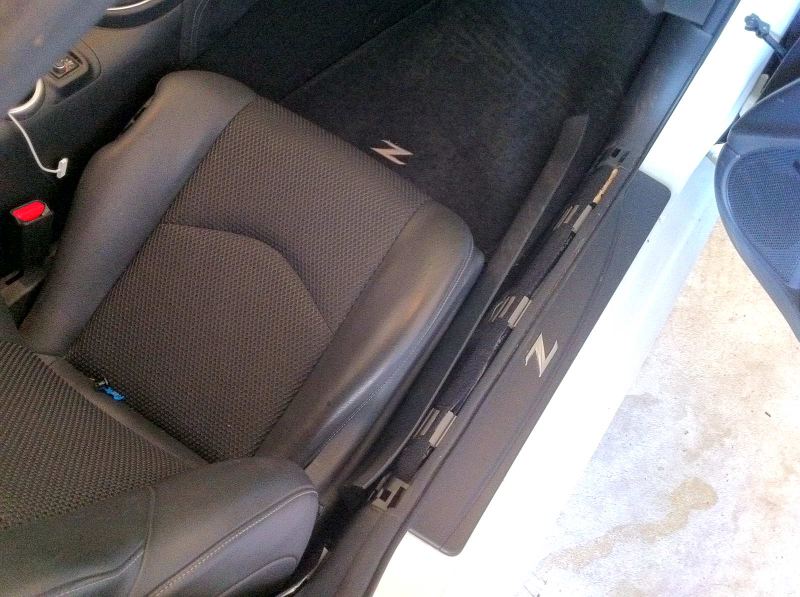
| 1. Start out with the top fully closed. Push and hold the top open switch just until the back of the soft-top and the rear lid are in their upmost positions, then let go and turn the ignition fully off. IMPORTANT: Secure the roof mechanism with either a cardboard box or a piece of wood in the position shown. Otherwise they will sink down over time and block access! |
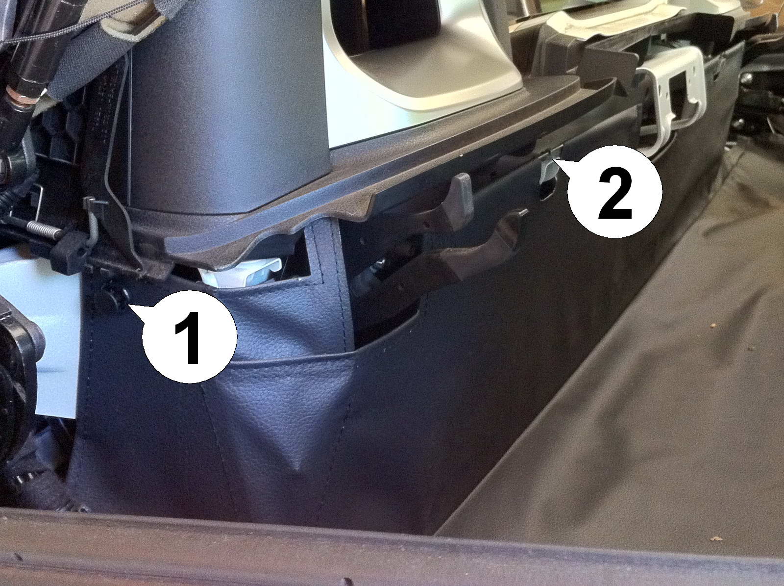
| 2. On the left side of the car remove the flexible covering by first pulling out the center piece of the rivet (1) and then pulling the bolt (2) straight up while pushing in on the sides (see next step). |
| 3. Close-up of the bolt. The locking mechanism can be seen on both sides. |
| Installation - Steps 4-6 | |
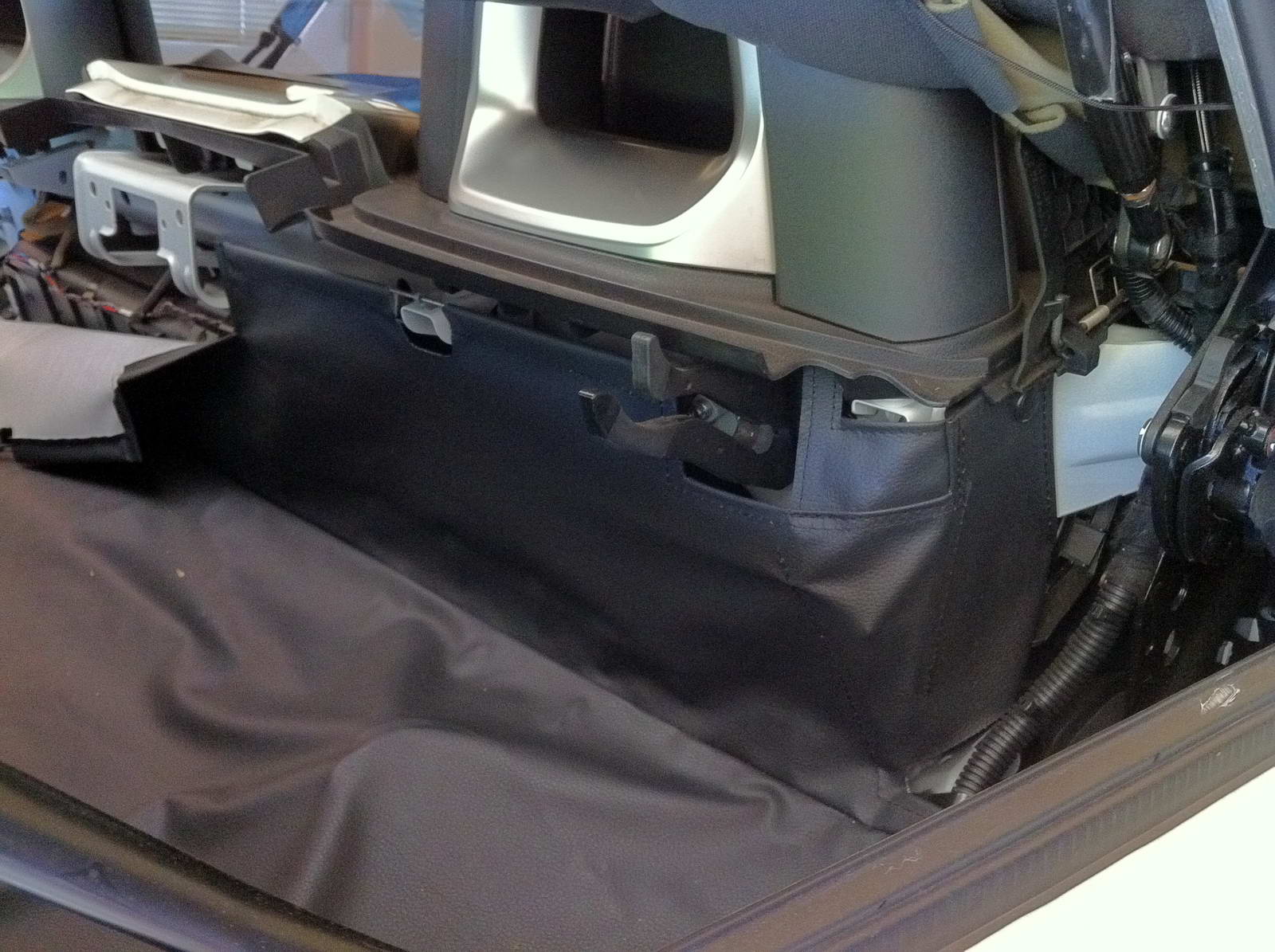
| 4. Same procedure on the right side. Remove the rivet and the locking bolt, then fold the entire cover back. |
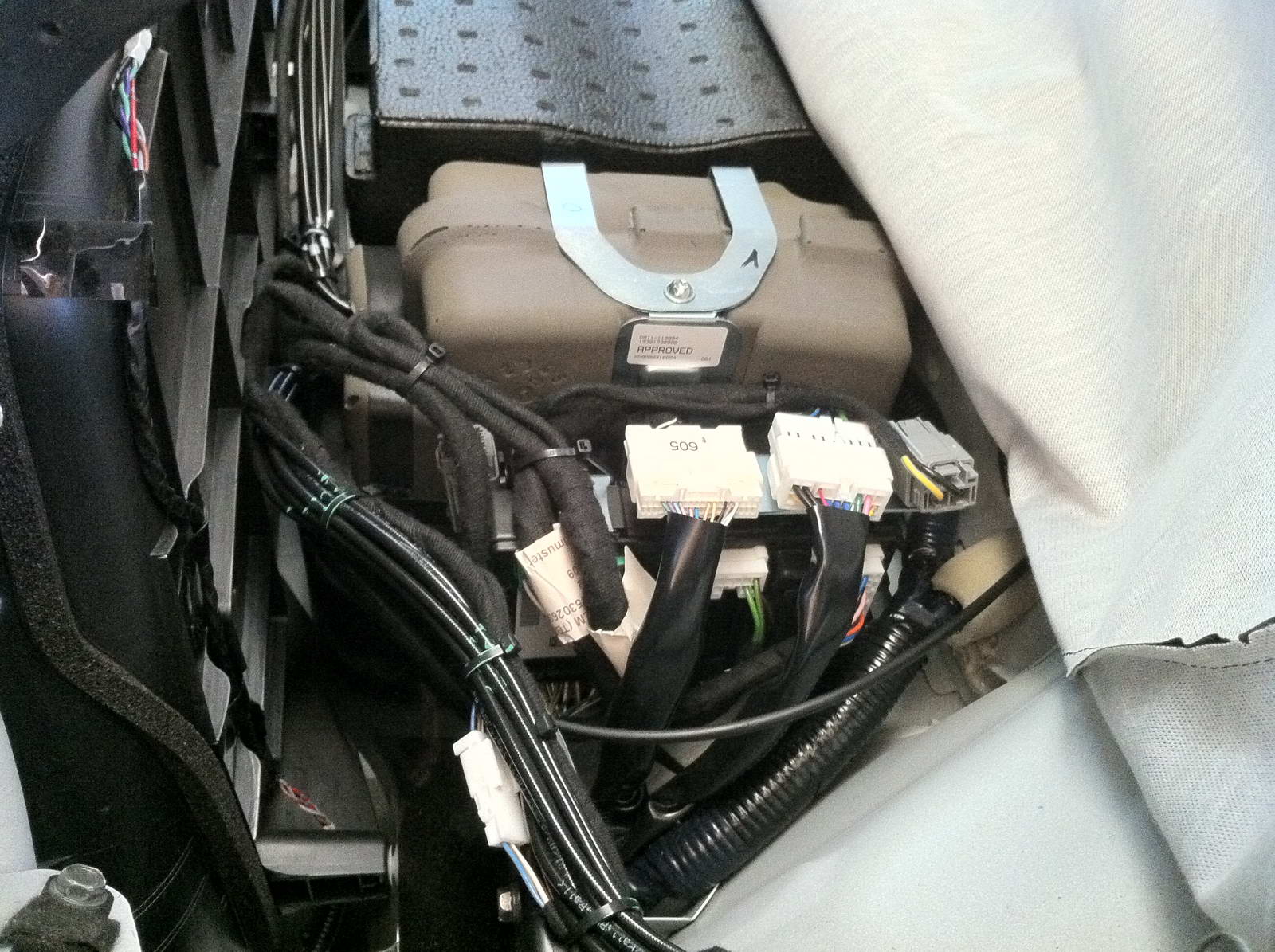
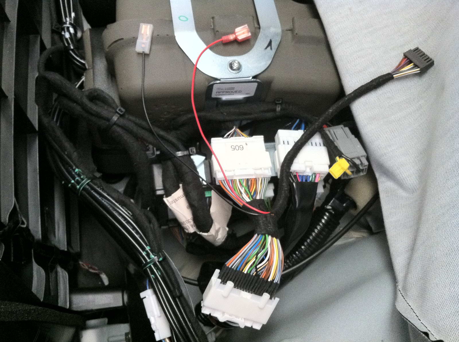
| 5. Back on the left side, the top control unit is directly under the cover just removed. There are two large white connectors with many thin wires and one smaller grey connector with only two thicker wires going to it. |
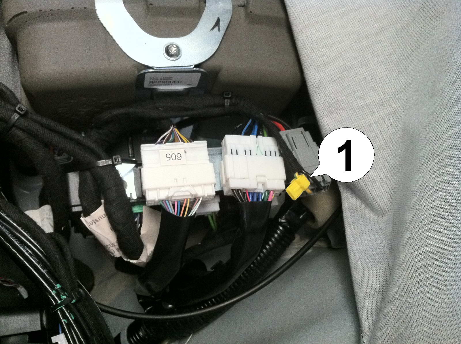
| 6. Attach the supplied yellow wire tap (1) to the power wire as shown. This wire is sometimes red and sometimes yellow/green. The power wire should always be the one that enters and leaves the connector pair on the left and must be a color other then black. |
| Installation - Steps 7-9 | |
| 7. Remove the left white plug and connect the module wiring harness in between as shown. Make sure all plugs latch securely. |
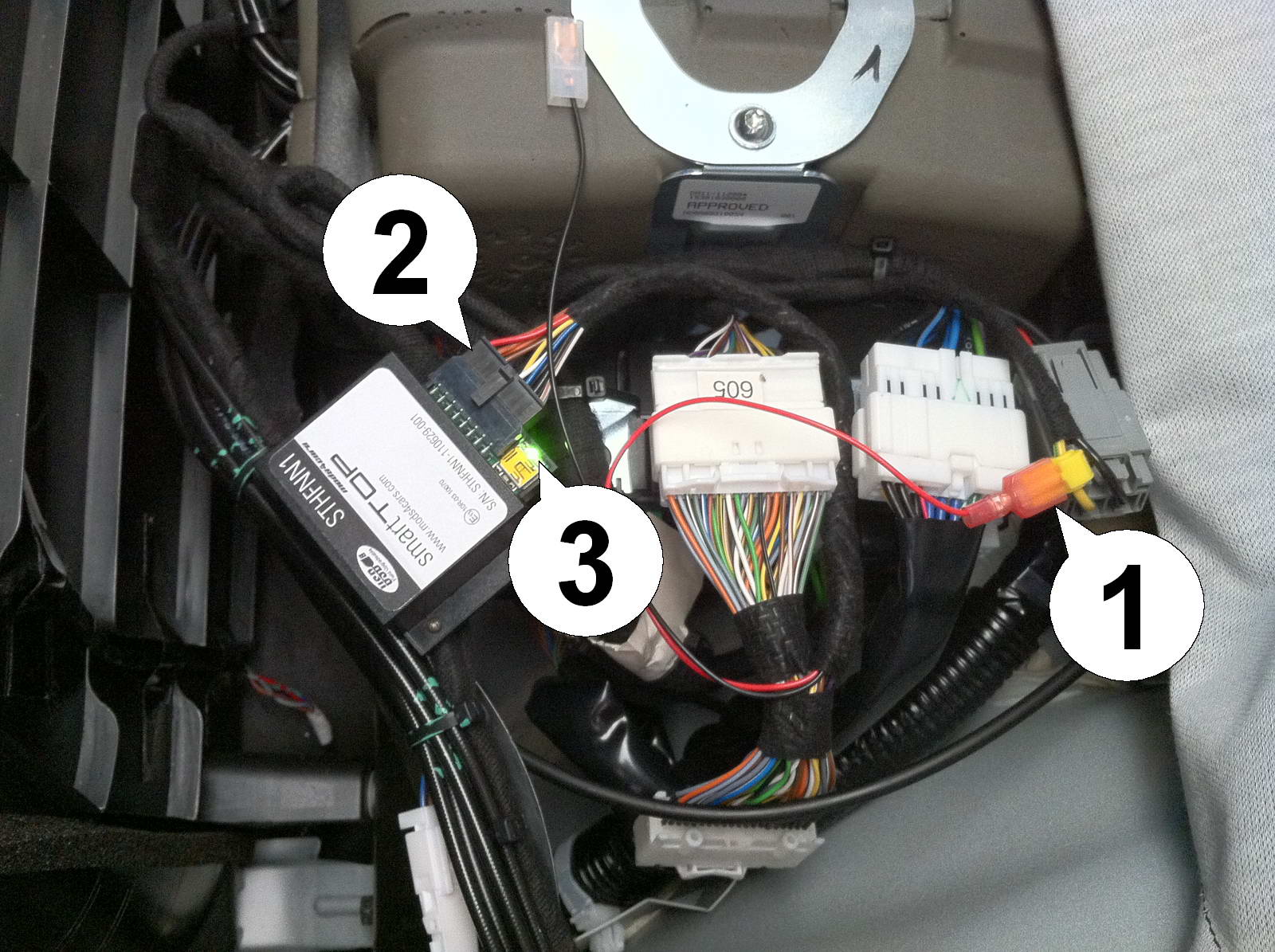
| 8. Now connect the power plug (1) to the yellow tap first (making sure the metal blade slides all the way into the slot), then connect the module to the black connector (2) on the harness. The green LED (3) should immediately light up for about a second (module boots up). Tap the unlock button on the remote once and the LED should now blink, indicating that the module is receiving data. This concludes the first half of the installation. |
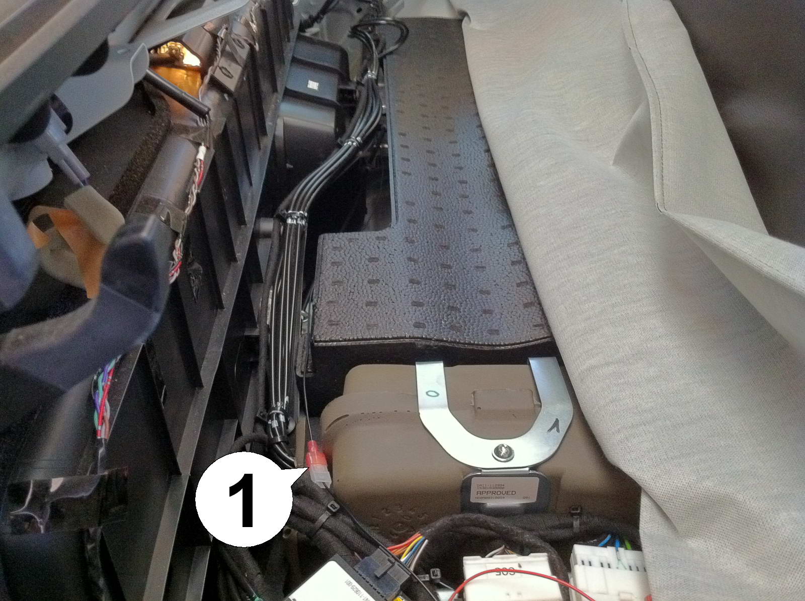
| 9. The second half of the installation deals with the long black wire, which must be run to the body control unit in order for the smarttop module to be able to control the windows. Connect one plug with the matching connector (1) on the module harness and run the wire over to the right side of the car. IMPORTANT: On RHD cars (UK, Australia, Asia etc) the control unit is in the front left. It is always under the passenger kickpanel. For these cars please mirror all following instructions and run the wire along the left side of the car. |
| Installation - Steps 10-12 | |
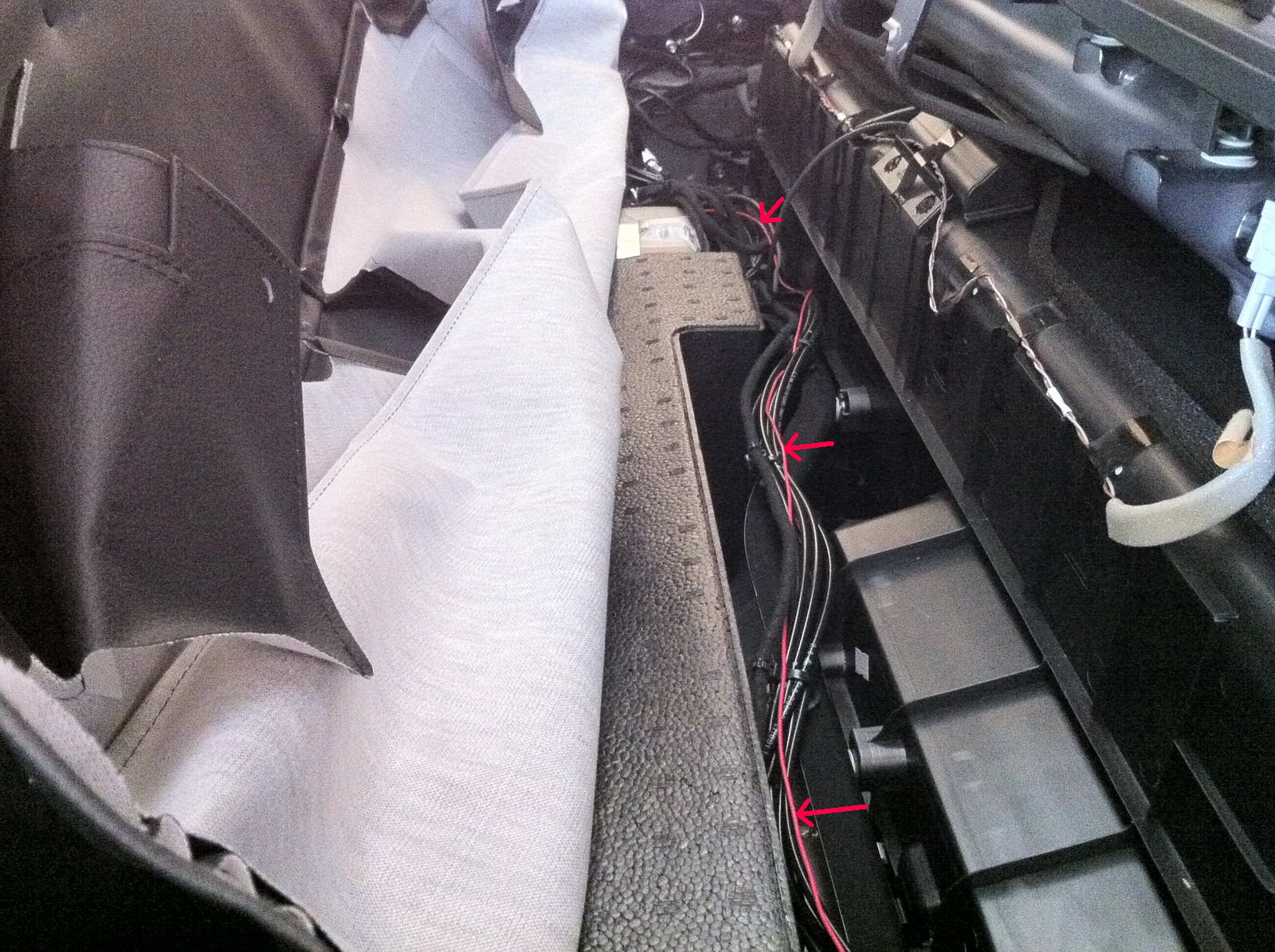
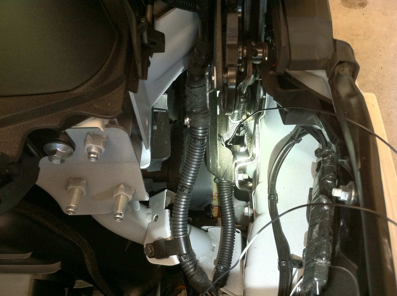
| 10. Back on the right side of the car, grab the wire and run it alongside the existing wiring harnesses as shown (for better visual a red wire is shown here!) all the way into the corner. |
| 11. Remove the plastic cover as shown by pullig up hard from the inside. It is snapped into place. |
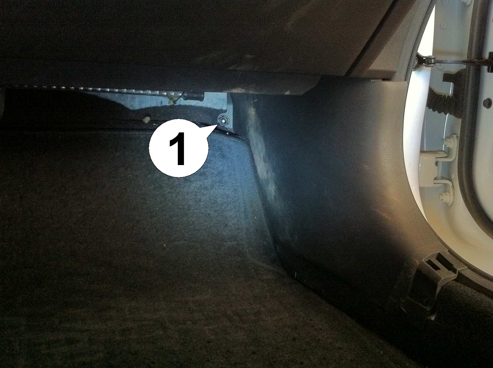
| 12. Remove the kick panel by unscrewing the plastic nut (1). It can easily be removed by hand. |
| Installation - Steps 13-15 | |
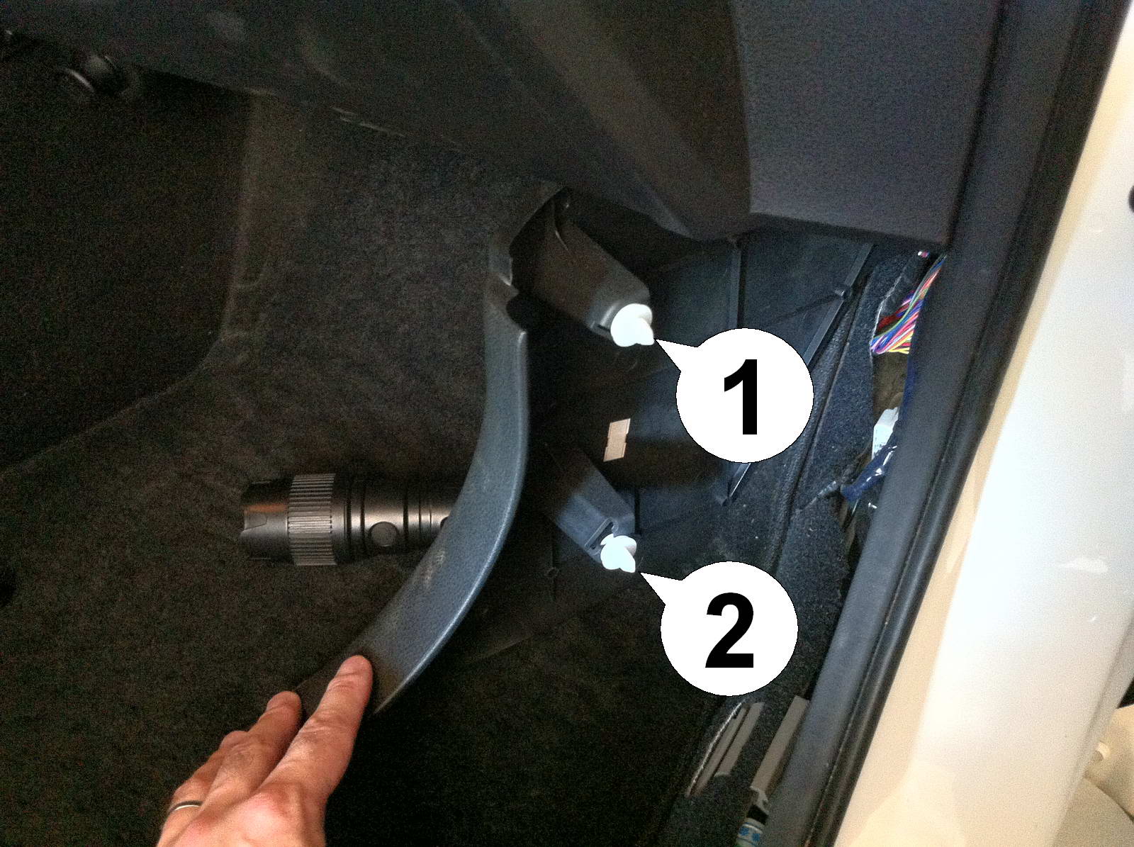
| 13. Push the front of the kick panel towards the center of the car. it is snapped into place with two bolts (1) and (2). |
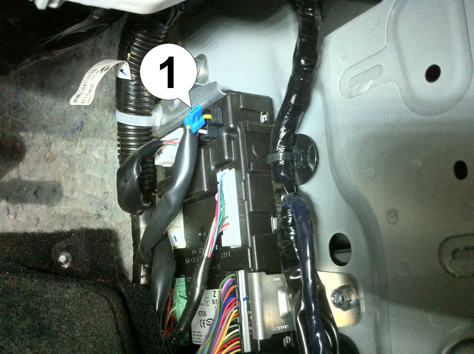
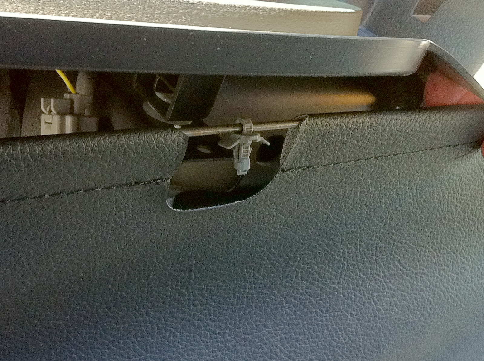
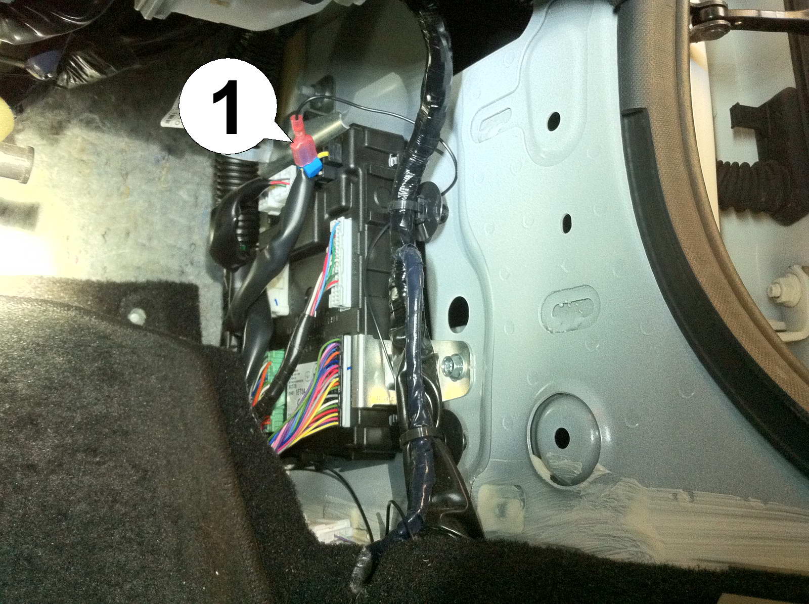
| 14. At the control unit behind the panel, attach the blue wire tap to the yellow wire (1) all the way at the top as shown. IMPORTANT: The wire POSITION is important. On some models the wire colors may not match up with the ones shown in the picture. Please tap the wire all the way in the upper right corner. |
| 15. Now run the black wire from the back alongside existing harnesses under the top mechanism. A wire hanger or patience and skill in directing the wire towards the front will be helpful. |
| Installation - Steps 16-18 | |
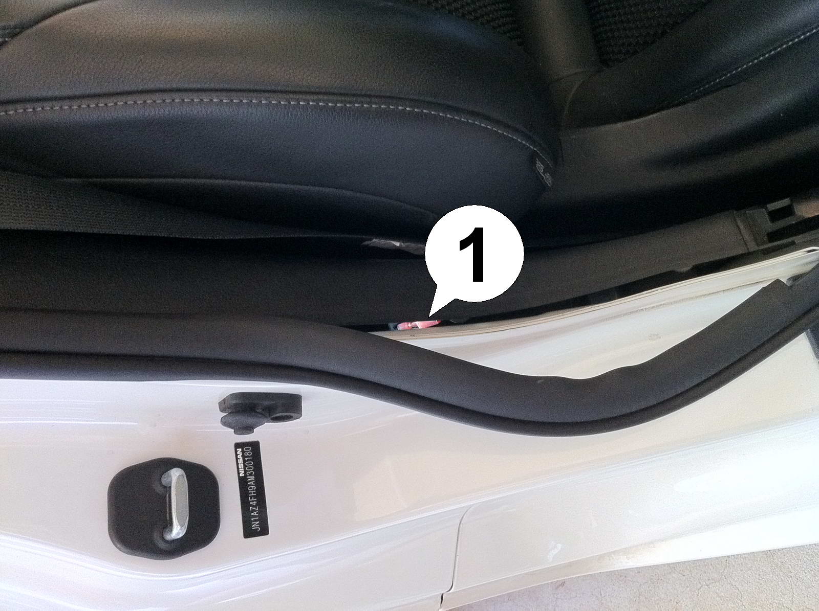
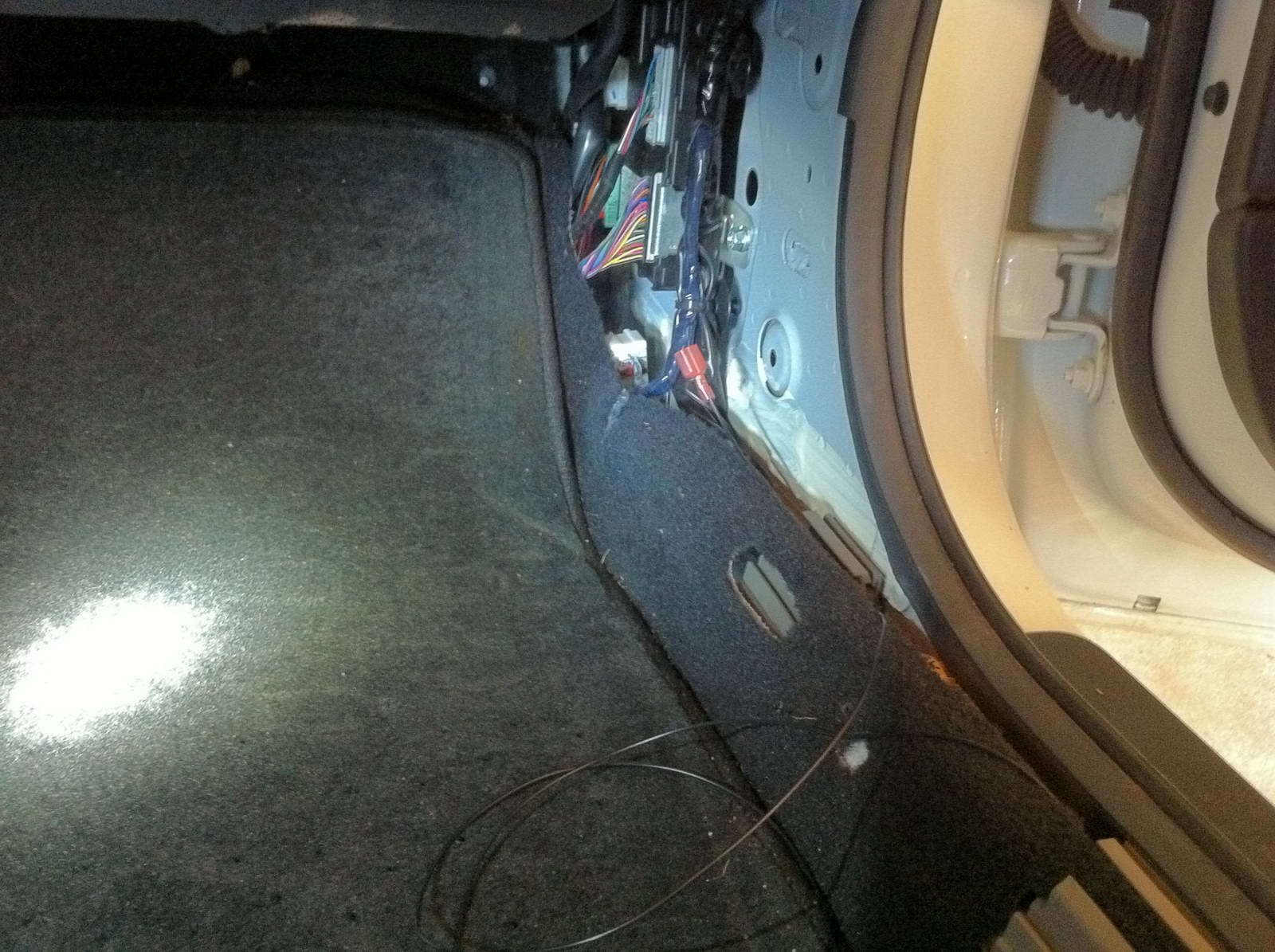
| 16. Remove the rubber seal in the bottom curve of the door frame. This is where the plug (1) should show up. |
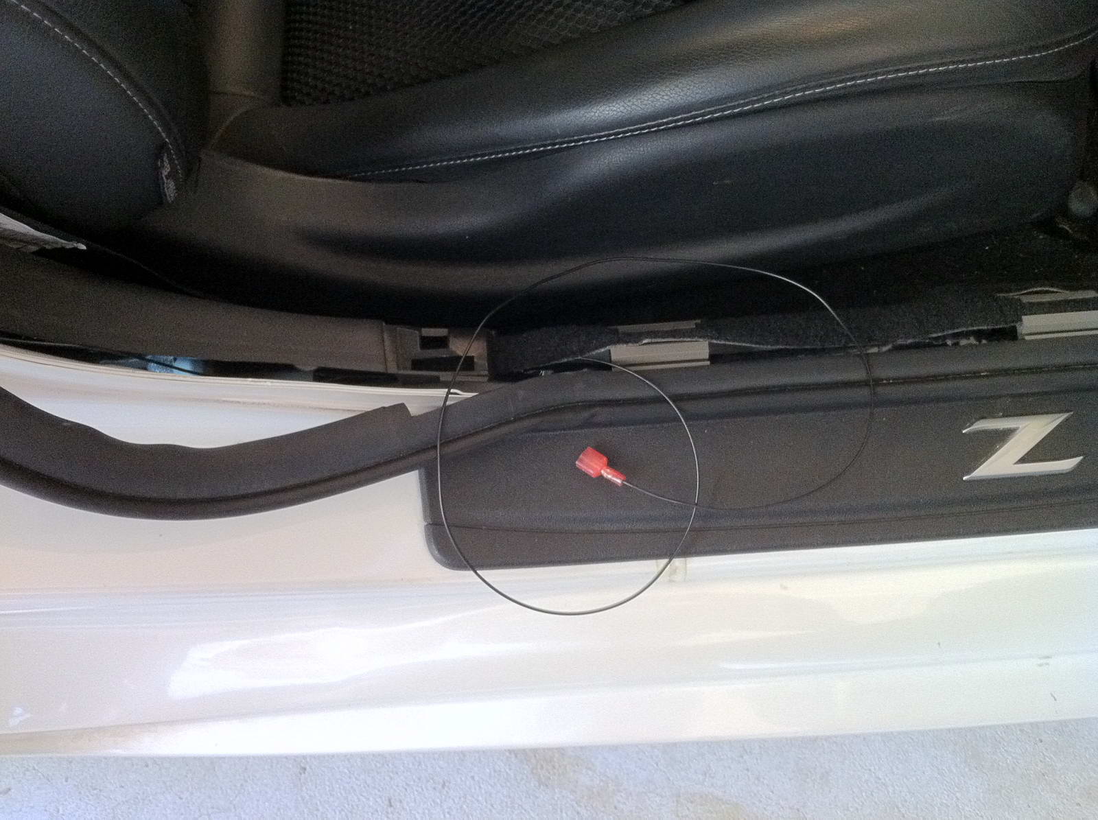
| 17. Fish the plug out from behind the plastic panel und pull the wire through, making sure it is nice and tight, running along existing wiring in the back and not in any area where it might get pinched by the top mechanism. |
| 18. Thread the wire through the large openings of the carpet holders all the way to the front. |
| Installation - Steps 19-21 | |
| 19. Pull the wire tight and make sure it runs parallel to the existing wiring from where it emerges behind the plastic cover and that it is clear everywhere for parts removed earlier to be put back into place. |
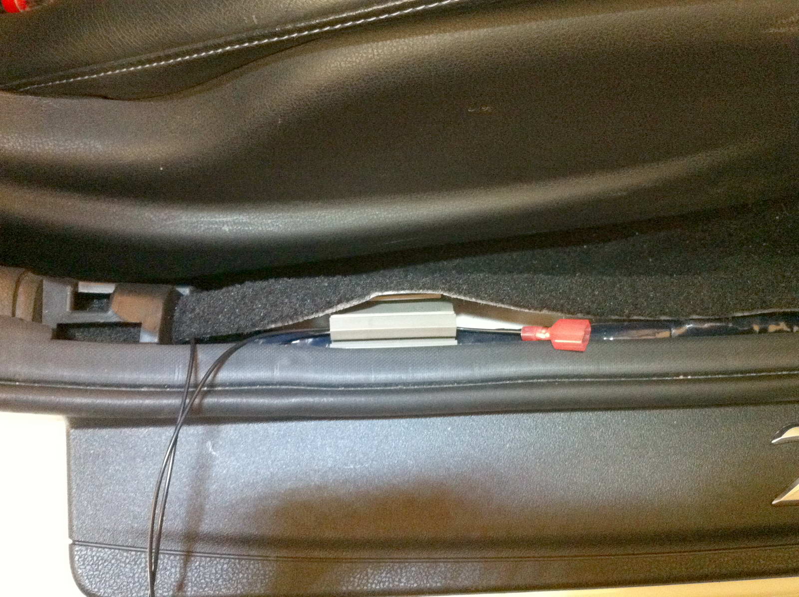
| 20. Connect the plug to the blue wire tap (1), again making sure the metal blade slides all the way into the slot. This concludes the second half of the installation. Lastly, put everything back together in the back, re-install the bolts and carpet rivets on the sides, push the rubber seal back into place, re-attach the kick panel and the cover piece. Now the module can be configured according to our Operation and Programming manual and is ready for use. |
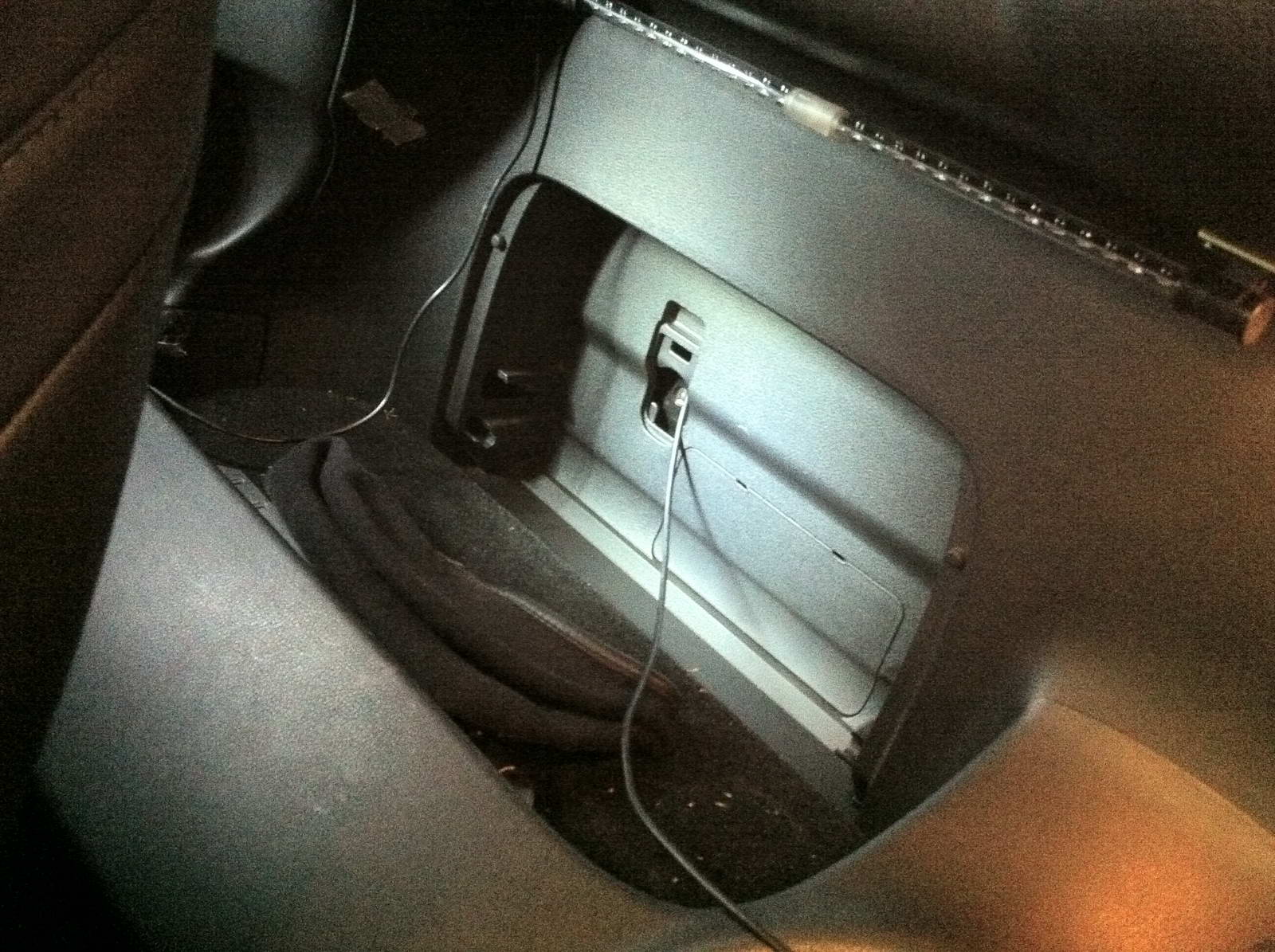
| 21. Optionally the USB cable can be permanently installed in the car and run from the module through the hole behind the fold-out storage compartment behind the right seat where it is easily accesible for configuration or firmware updates via laptop. |