INSTALLATION
STAXFI1
Comfort Roof Control Module for
v1.xx
Further information and manuals for all products can be found on our web site
w w w . m o d s 4 c a r s . c o m
PLEASE READ THE COMPLETE MANUAL CAREFULLY BEFORE USING THIS PRODUCT.
INSTALLATION |
|
|
STAXFI1 Comfort Roof Control Module for v1.xx |
Further information and manuals for all products can be found on our web site w w w . m o d s 4 c a r s . c o m |
| We explicitly point out that all functions of this control unit should be used only while exercising caution and responsibility. We can NOT be held liable for any damage or injury caused by installing or using this product. PLEASE READ THE COMPLETE MANUAL CAREFULLY BEFORE USING THIS PRODUCT. |
| Important Information. READ BEFORE INSTALLING! | |
|---|---|
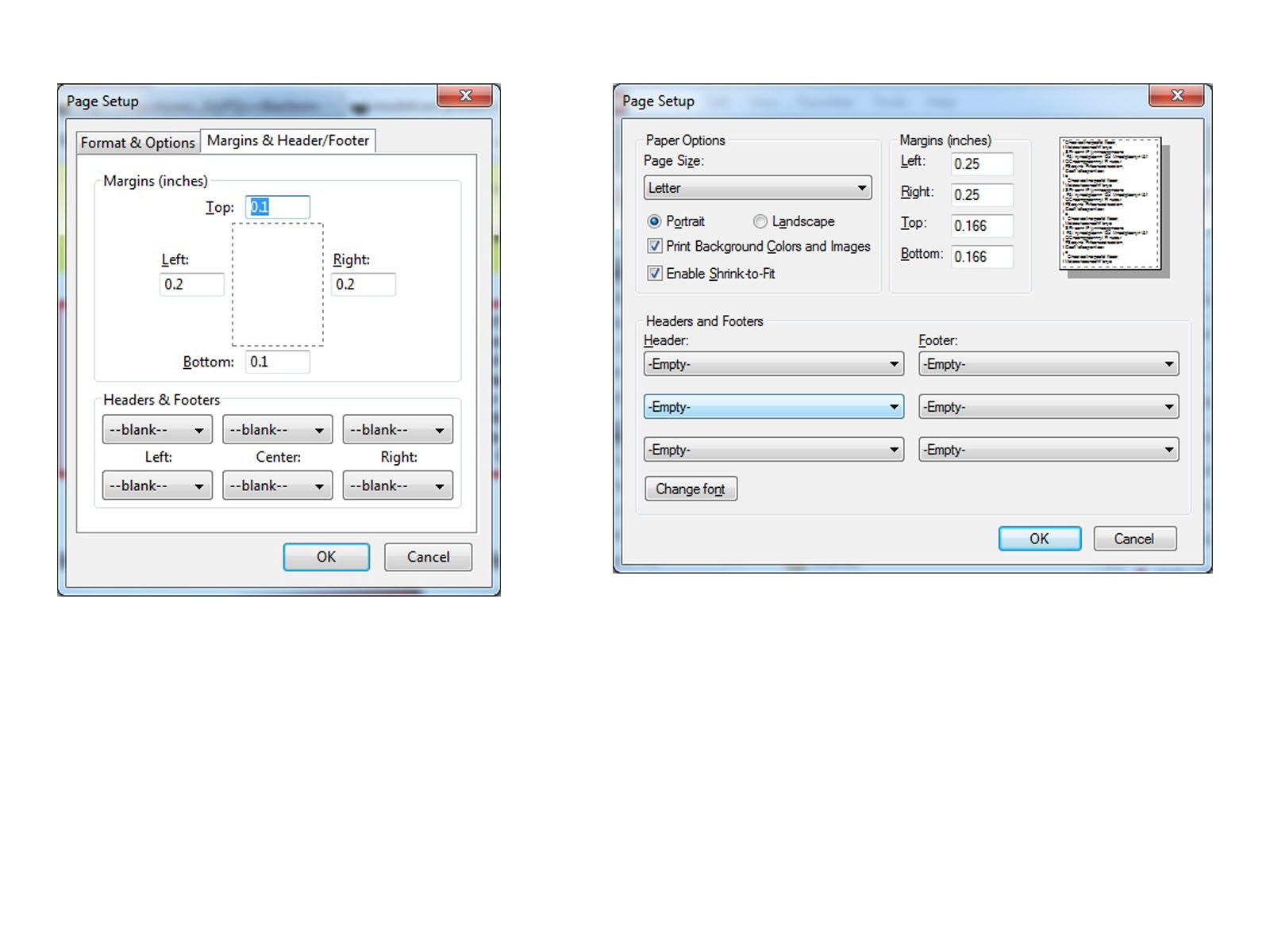
| PRINTING THIS MANUAL This manual is designed to produce completely filled pages. In order to get best print results, simply set the borders to minimum settings in the browser's page setup menu and disable headers and footers. Activate the print preview and if necessary decrease the zoom level until all pages are shown correctly. ALL IMAGES CAN BE CLICKED FOR FULL SIZE in the browser. |

| TROUBLE SHOOTING - NEED TO CONTACT US? If you run into any problems after installing the module, please go over the manual again in great detail, clicking every photo for full size! We now have a full Knowledge Base with Support Ticket system available online at www.mods4cars.com/support If you need to contact us, the best and fastest way to do so is by opening a support ticket there |
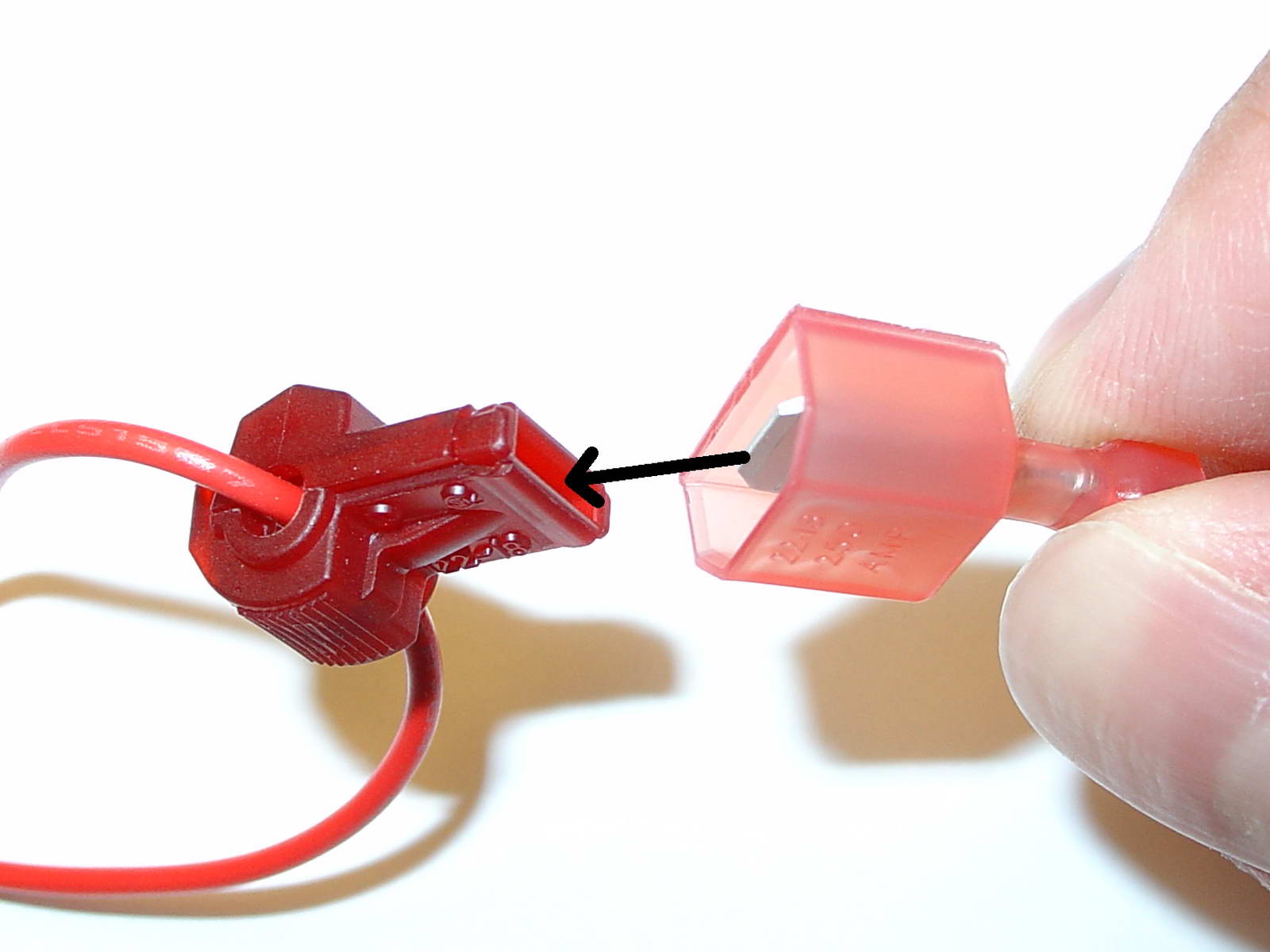
| USE OF THE 3M WIRE TAPS This module is installed using the 3M wire taps very popular with 12V aftermarket industry for their reliability and durability. The most common problem during installation is a bad contact between the plugs from the supply wires and the wire taps. Please make absolutely sure that the metal blades of the plugs slide into the slots of the t-taps. It happens that the blade "misses" the slot and the connection looks correct, but doesn't make electrical contact! The T-taps come in RED (for thin wires), BLUE (for medium wires) and YELLOW (for thick wires). To test if you installed the module correctly after all wires are connected, turn the ignition fully on and watch the green LED on the module. It should blink (flash) to signal a correct installation. If the LED either does not turn on or stays on permanently, there is a bad contact or a missing connection! See detailed explanation of the DATA LED. |
| Installation - Steps 1-3 | |
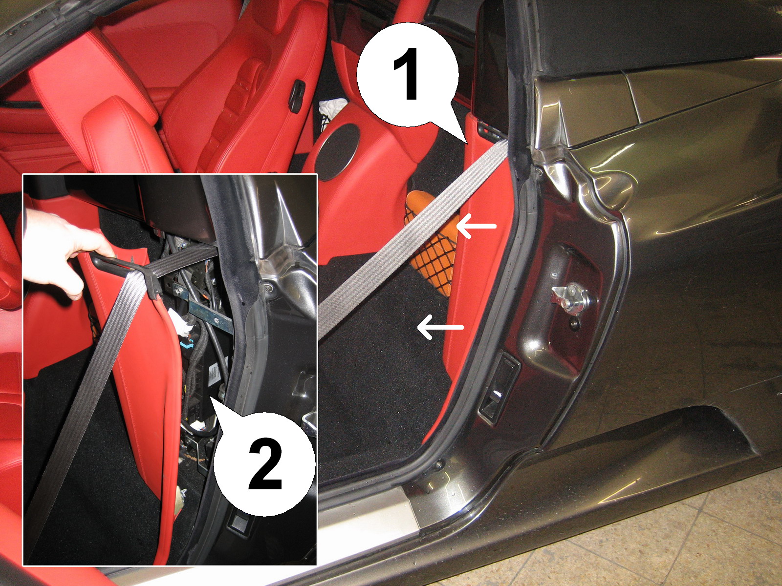
| 1. IMPORTANT: Turn ignition off, and pull key from ignition lock before installing the module! Move the driver's seat all the way up and tilt forward. Remove the side panel (1) behind the driver's seat by pulling it out to the front of the car. Behind it is the top controller unit (2). |
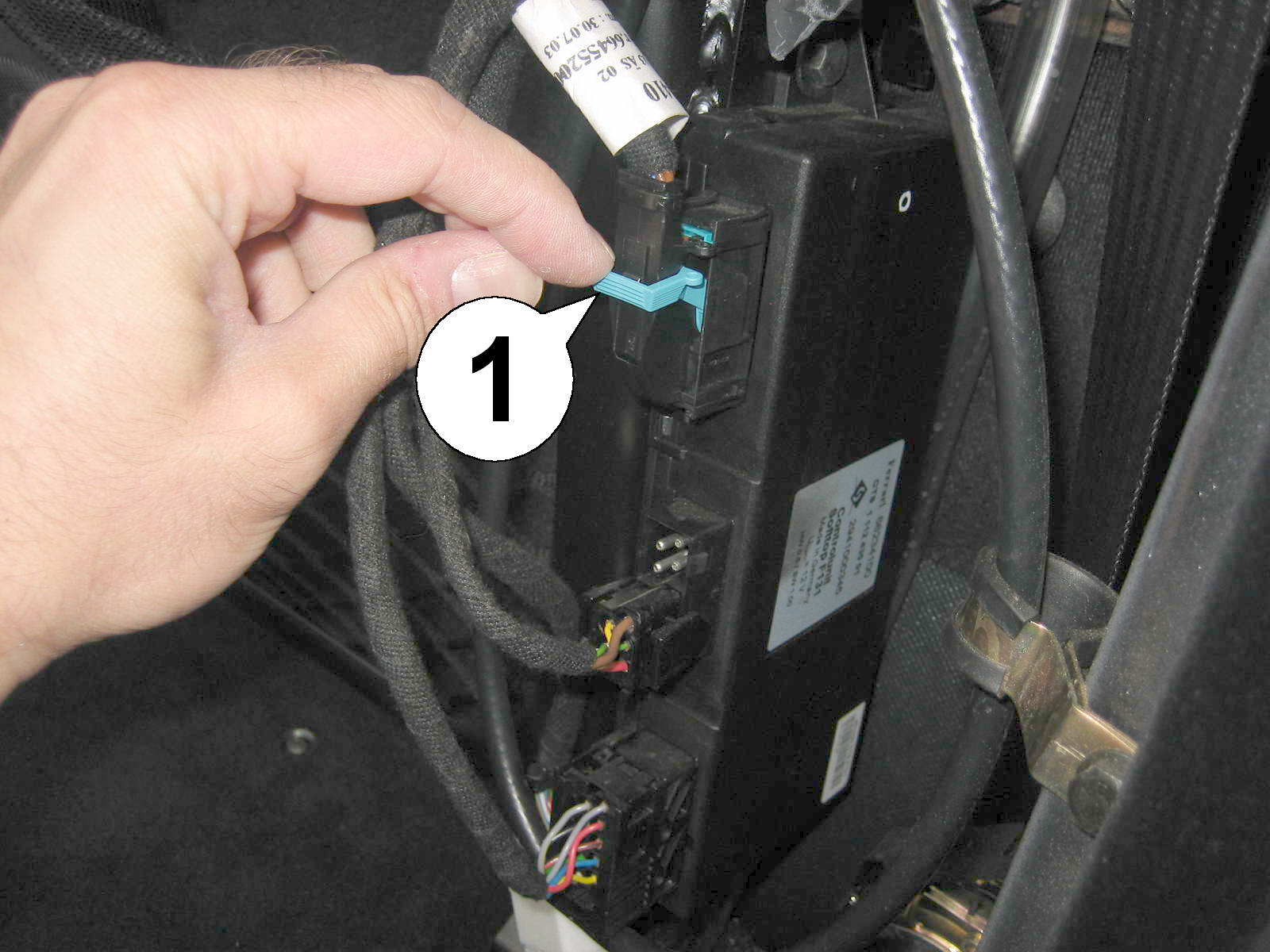
| 2. Push the (usually blue colored) bracket (1) on the topmost plug down (while pushing the small latch in the middle of the plug in) to eject the plug from the top controller. |
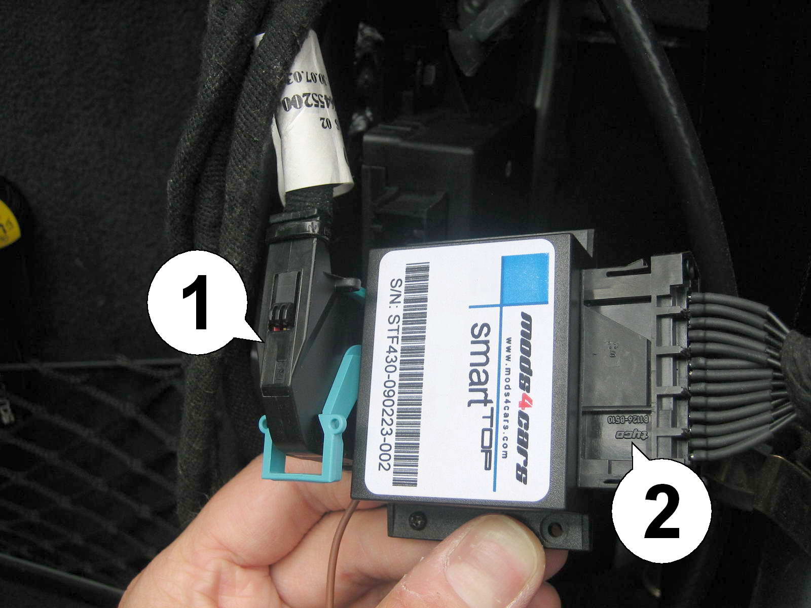
| 3. Connect the plug (1) just removed from the top controller exactly as shown with pin header on the bottom of the smartTOP module. Make sure all pins mate with the holes in the plug and no pin gets bent. Insert the top connector of the smartTOP into the socket of the wire extender, so that the "Tyco" logo (2) is visible / facing up. |
| Installation - Steps 4-6 | |
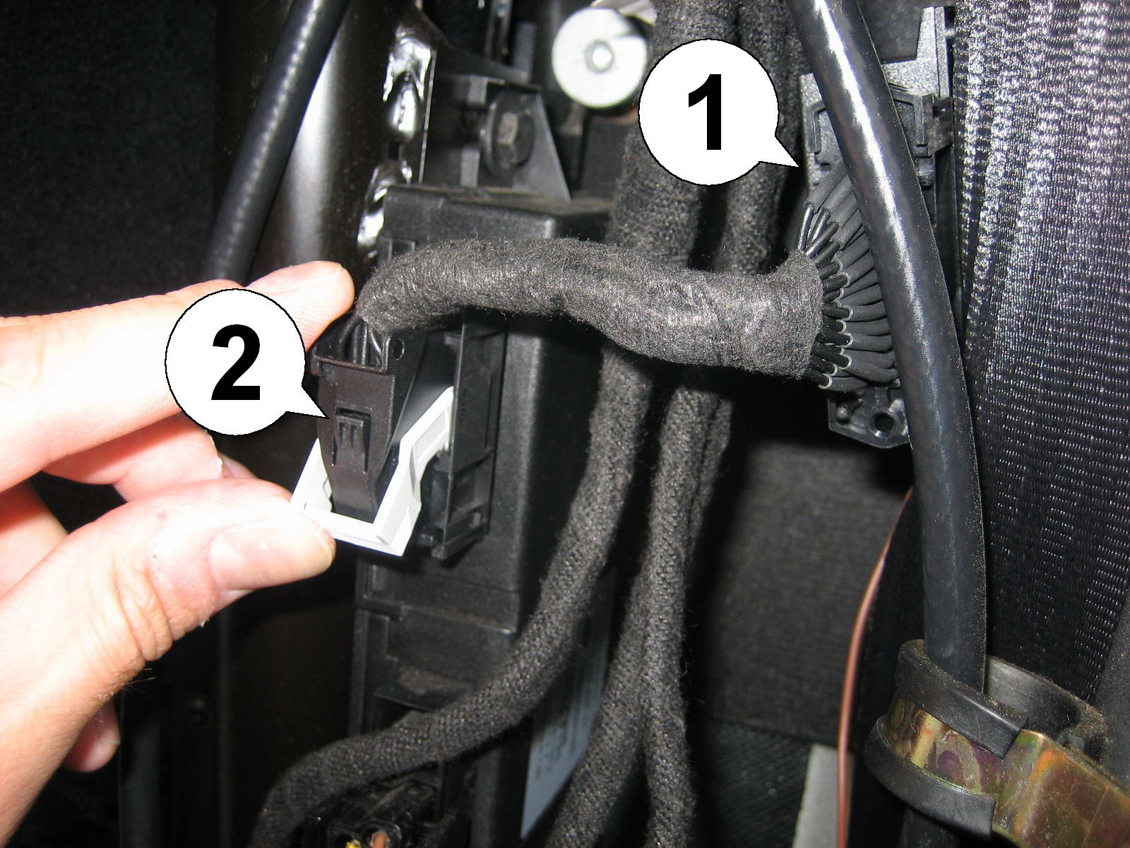
| 4. Place the smartTOP module (1) in the void to the right of the top controller. Then insert the plug from the wire extender (2) into the socket on the top controller and move the (white) bracket up to lock it in place. |
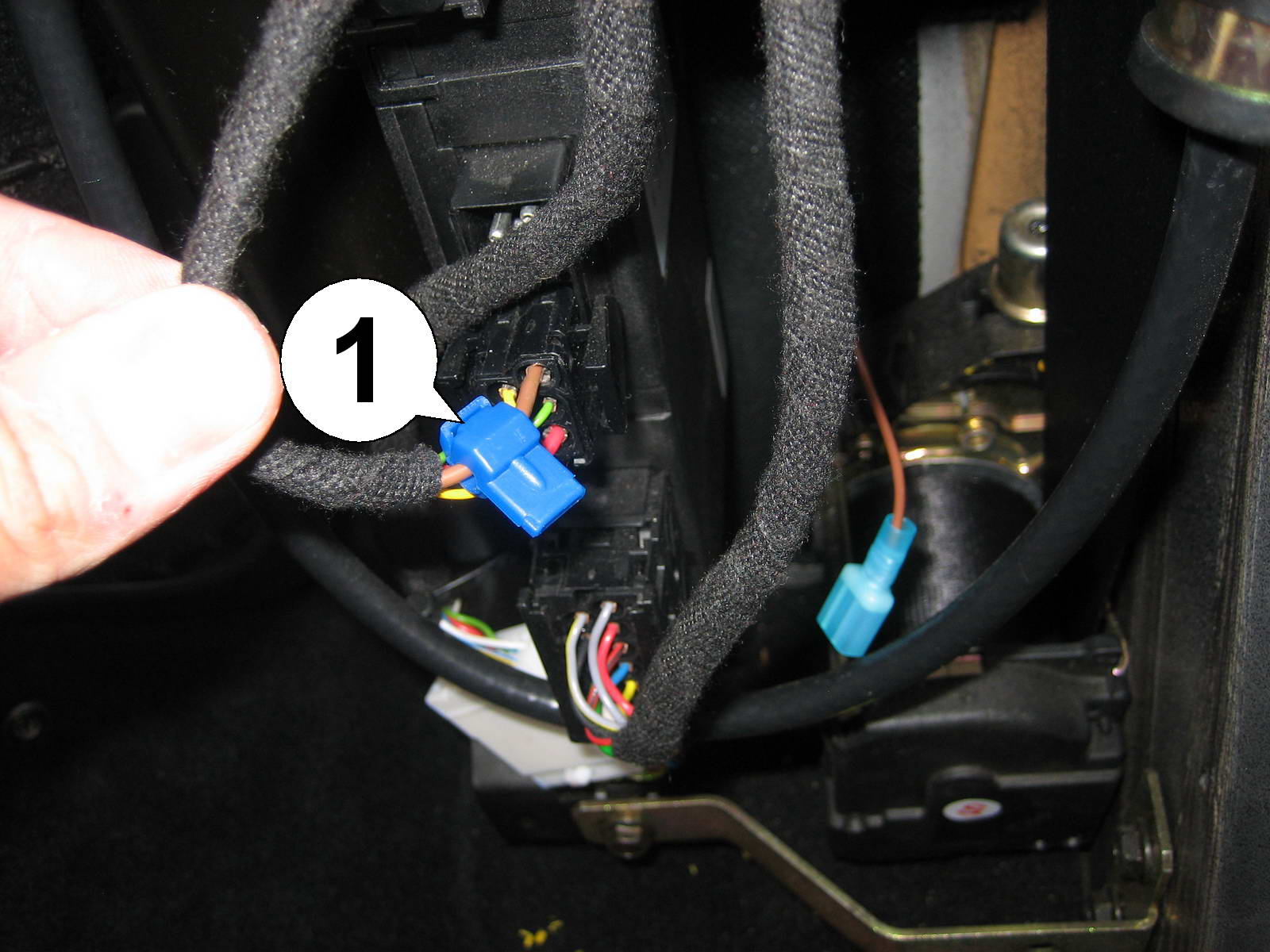
| 5. Attach the supplied blue T-tap (1) to the solid brown wire on the middle plug. Best use combination pliers and make sure that it snaps into place with an audible click. |
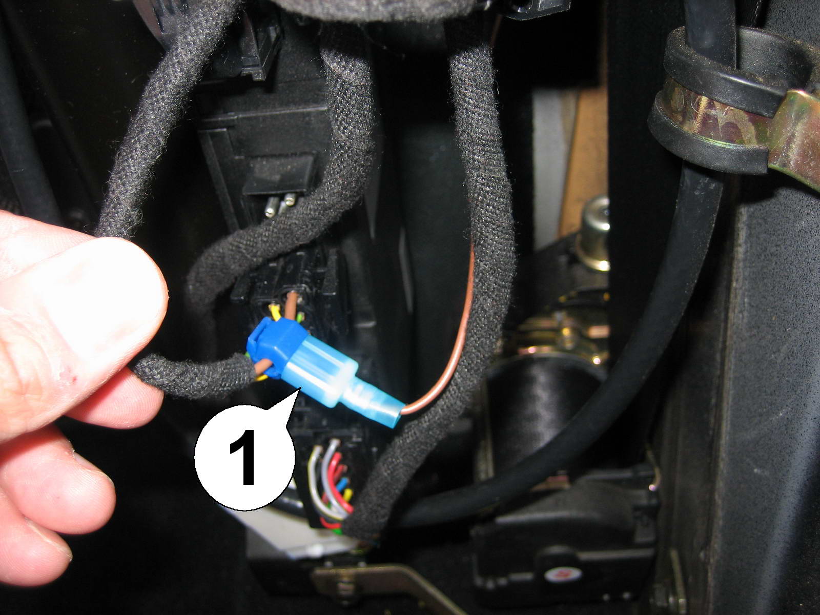
| 6. Now connect the ground plug (1) from the smartTOP to the T-tap, pushing it all the way in and making sure that the metal blade in the plug actually slides into the slot of the tap. Now attach the side panel in its original place and set up the module according to our operation and programming manual. Done. |