INSTALLATION BMW Z4 (E85)
STLFBW7
Comfort Roof Control Module for
v1
Further information and manuals for all products can be found on our web site
w w w . m o d s 4 c a r s . c o m
PLEASE READ THE COMPLETE MANUAL CAREFULLY BEFORE USING THIS PRODUCT.
INSTALLATION BMW Z4 (E85) |
|
|
STLFBW7 Comfort Roof Control Module for v1 |
Further information and manuals for all products can be found on our web site w w w . m o d s 4 c a r s . c o m |
| We explicitly point out that all functions of this control unit should be used only while exercising caution and responsibility. We can NOT be held liable for any damage or injury caused by installing or using this product. PLEASE READ THE COMPLETE MANUAL CAREFULLY BEFORE USING THIS PRODUCT. |
| Important Information. READ BEFORE INSTALLING! | |
|---|---|
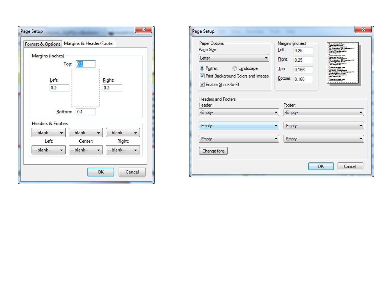
| PRINTING THIS MANUAL This manual is designed to produce completely filled pages. In order to get best print results, simply set the borders to minimum settings in the browser's page setup menu and disable headers and footers. Activate the print preview and if necessary decrease the zoom level until all pages are shown correctly. ALL IMAGES CAN BE CLICKED FOR FULL SIZE in the browser. |

| TROUBLE SHOOTING - NEED TO CONTACT US? If you run into any problems after installing the module, please go over the manual again in great detail, clicking every photo for full size! We now have a full Knowledge Base with Support Ticket system available online at www.mods4cars.com/support If you need to contact us, the best and fastest way to do so is by opening a support ticket there |
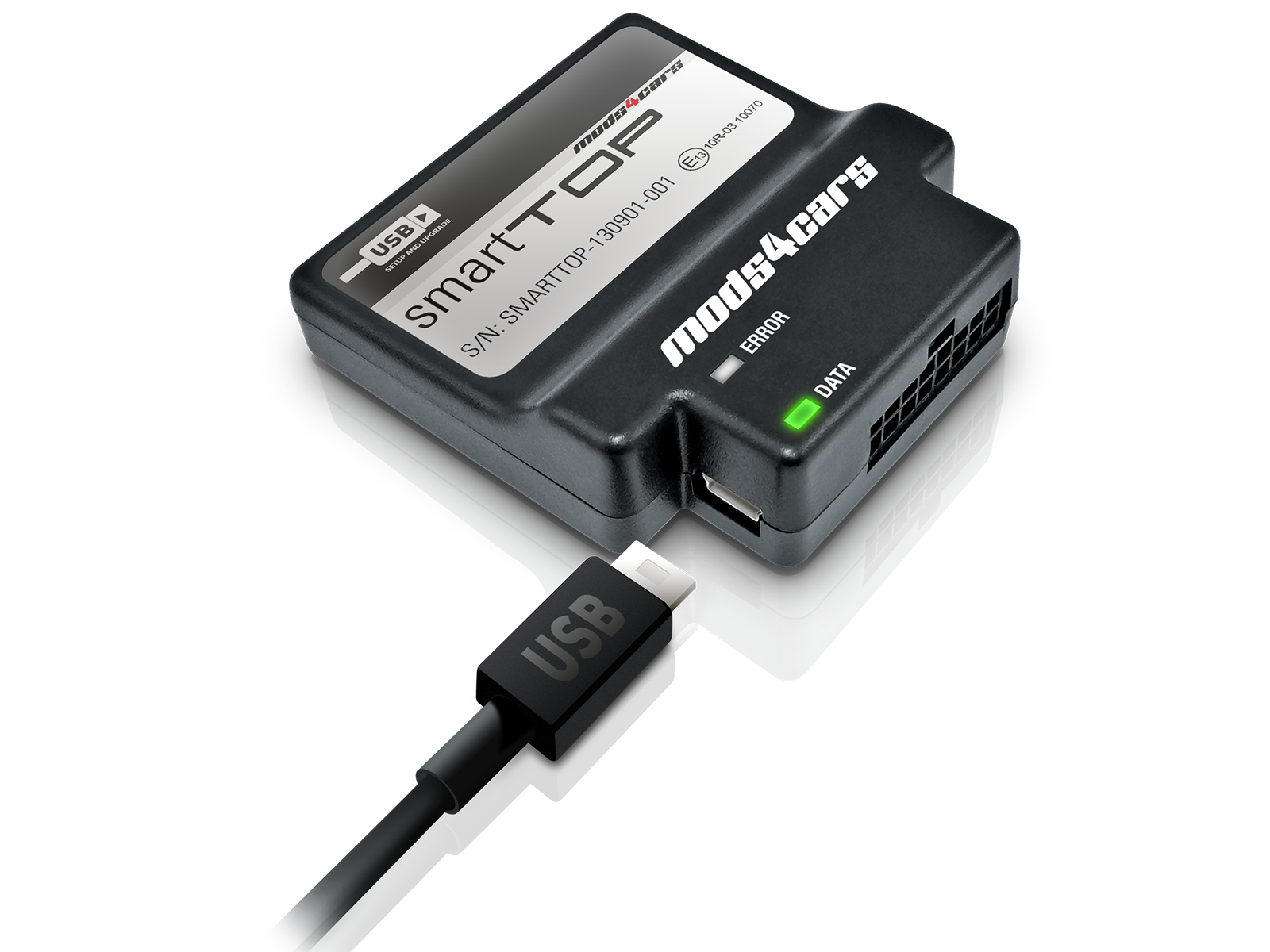
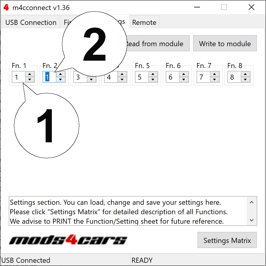
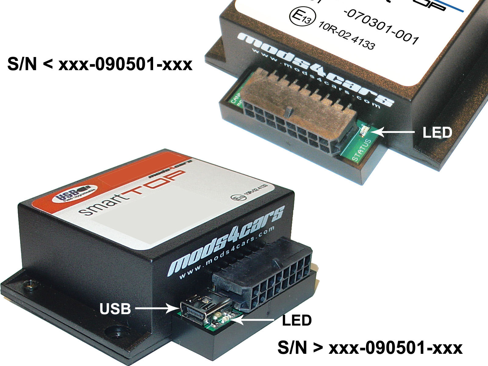
| This module comes with our USB Field Upgrade and Configuration Port! We recommend connecting it to a computer BEFORE YOU INSTALL and using our support app "m4cconnect" to do a quick firmware update check. M4cconnect as well as all other information regarding USB update and configuration can be found at www.mods4cars.com/usb. You can even configure and activate your favorite module functions and settings on screen before the module is installed in the car! It is a good idea to permanently install the USB cable with the module in the car, leaving the computer plug in an easily accessible spot for later use with a Wifi/3G/4G connected laptop. |
| IMPORTANT TROUBLESHOOTING TIPS If the top does not work properly or at all after installing the module, these tips can be very helpful: 1) Turn Function 1 (Main Switch) off (Setting 0). The module will be completely passive. If the problem still persists and the top won't work, check all connections. Please also check the green DATA LED on the module! 2) Function 2 now has a valet mode (Setting 2) on many modules. Valet mode completely disables opening of the top. Check the setting for function 2 and make sure the module is NOT in valet mode! IMPORTANT: Not all modules have the valet mode! Please check the Operation and Programming Manual! |
|
The green InstallAID™ LED signals a correct installation and shows the status of the module. On new modules this LED is labeled with DATA. LED OFF LED either dimly lit or flickering erratically LED permanently ON LED blinks |
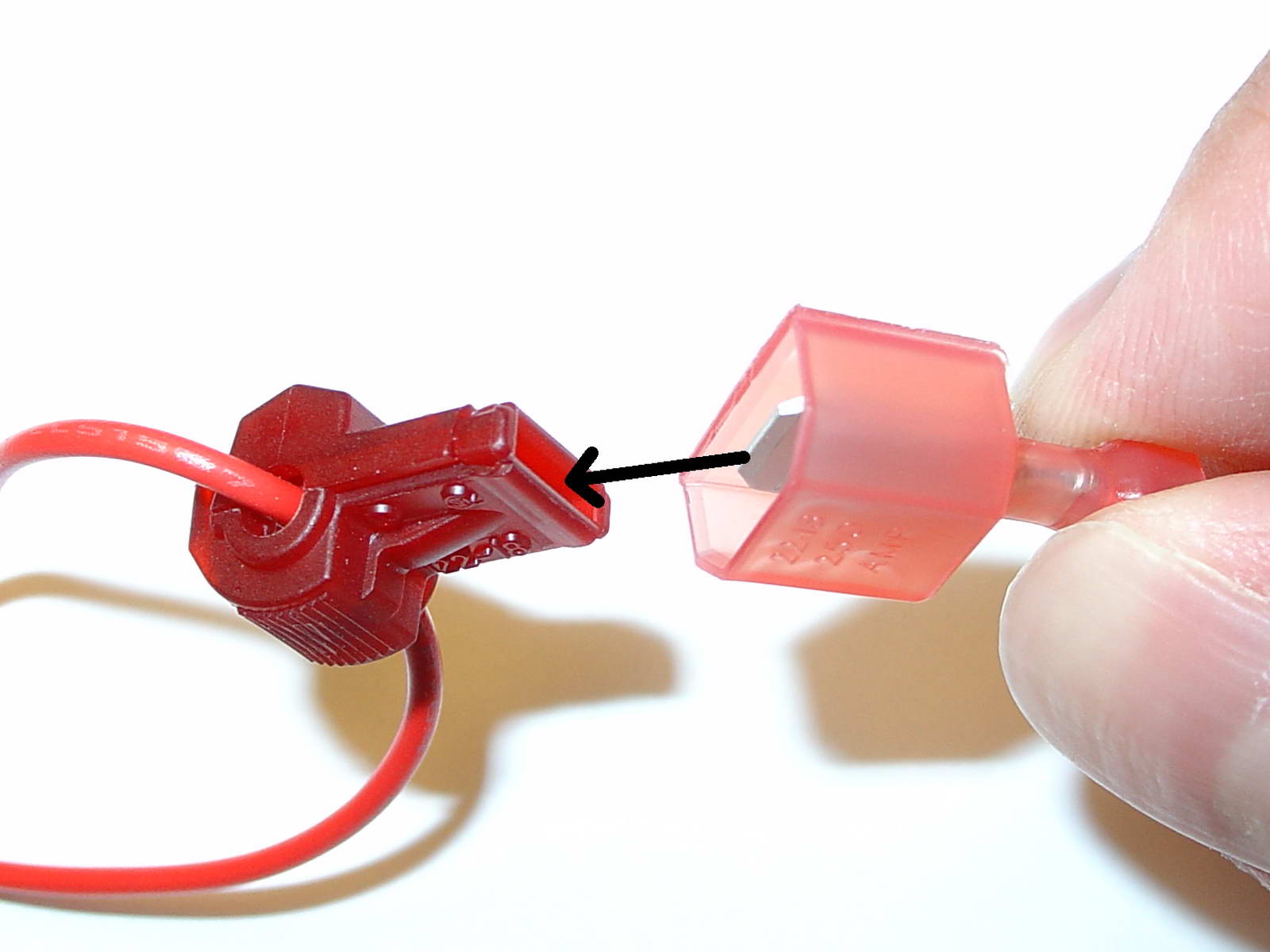
| USE OF THE 3M WIRE TAPS This module is installed using the 3M wire taps very popular with 12V aftermarket industry for their reliability and durability. The most common problem during installation is a bad contact between the plugs from the supply wires and the wire taps. Please make absolutely sure that the metal blades of the plugs slide into the slots of the t-taps. It happens that the blade "misses" the slot and the connection looks correct, but doesn't make electrical contact! The T-taps come in RED (for thin wires), BLUE (for medium wires) and YELLOW (for thick wires). To test if you installed the module correctly after all wires are connected, turn the ignition fully on and watch the green LED on the module. It should blink (flash) to signal a correct installation. If the LED either does not turn on or stays on permanently, there is a bad contact or a missing connection! See detailed explanation of the DATA LED. |
| Installation - Steps 1-3 | |
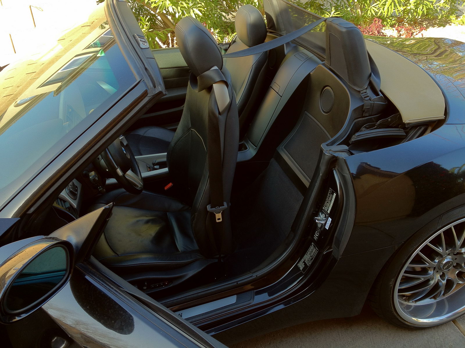
| 1. Start out by putting the top completely down and turning the ignition off. Move the driver's seat all the way up as shown. |
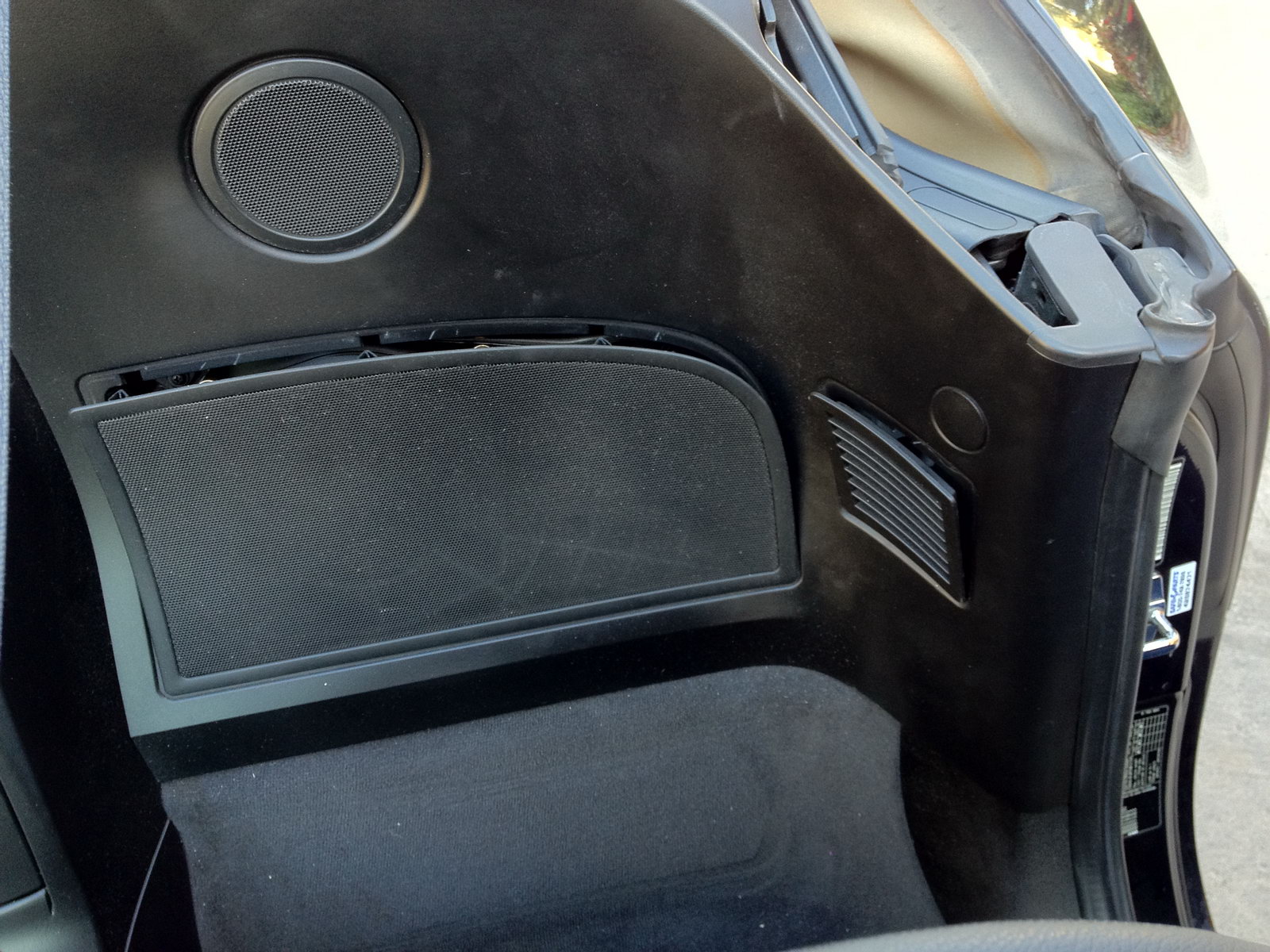
| 2. Open both access panels behind the left (driver's) seat by carefully prying them open on the top with a plastic tool or credit card. |
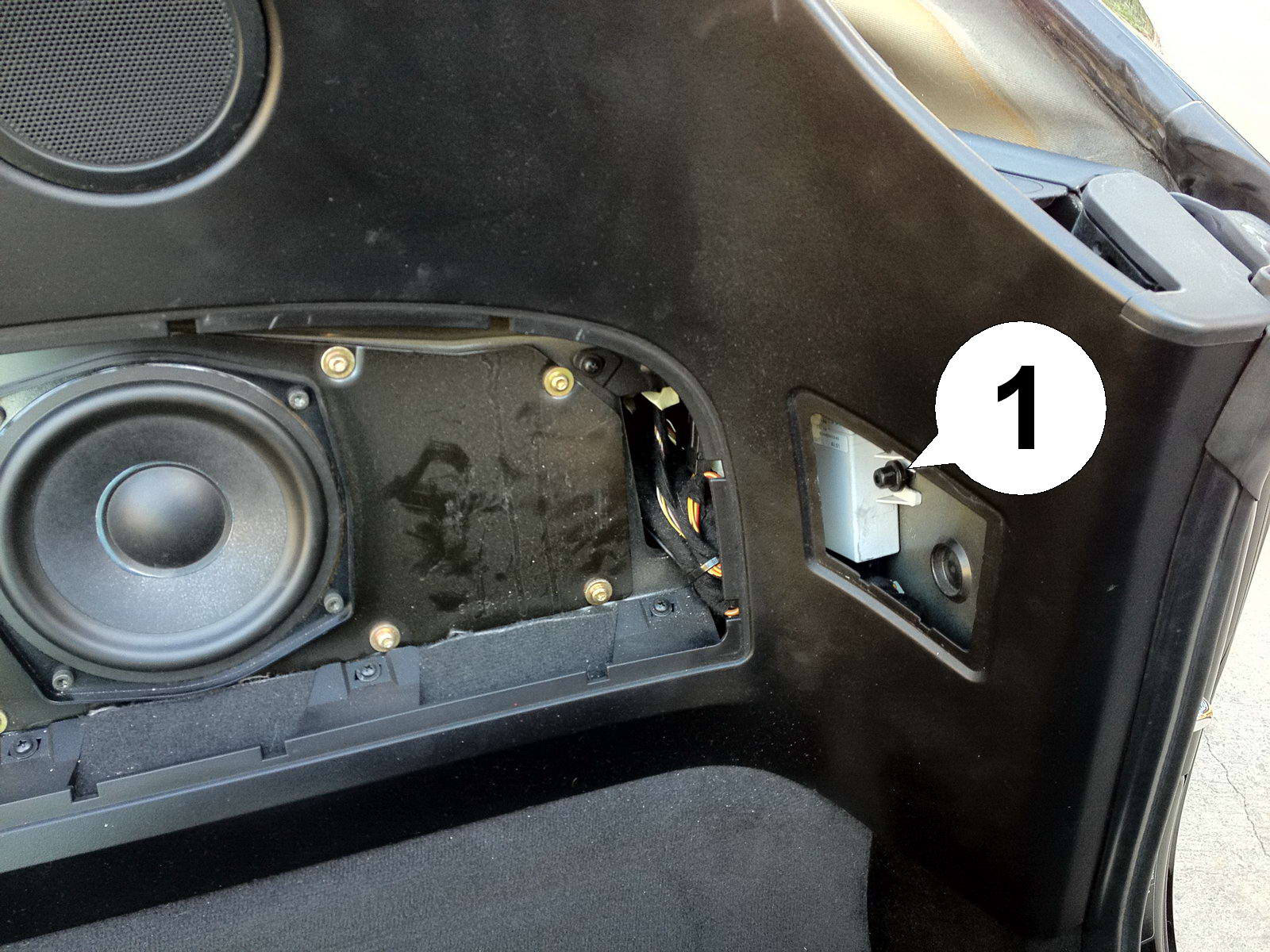
| 3. The white box in the corner is the top control unit. Remove the black 10mm nut (1). |
| Installation - Steps 4-6 | |
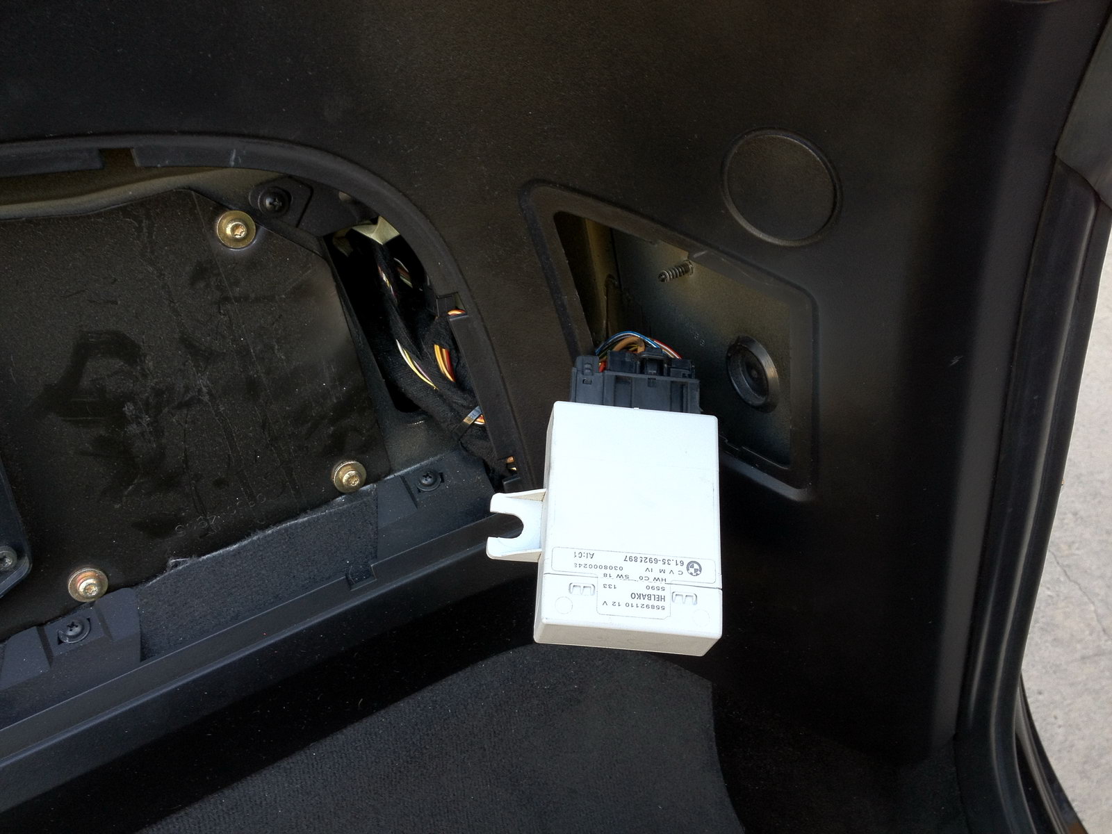
| 4. Wiggle the unit free and pull it out through the opening. |
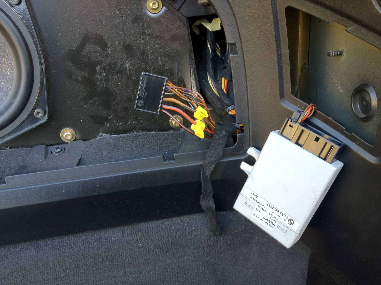
| 5. Disconnect the large plug (by pushing in the locking tabs on the sides while pulling) and run the wire harness through to the larger access panel. Remove some of the cloth tape for better access to the wires. Attach the two supplied wire taps with combination pliers. One to the thick brown wire for ground and one to the thick red/purple wire for power. |
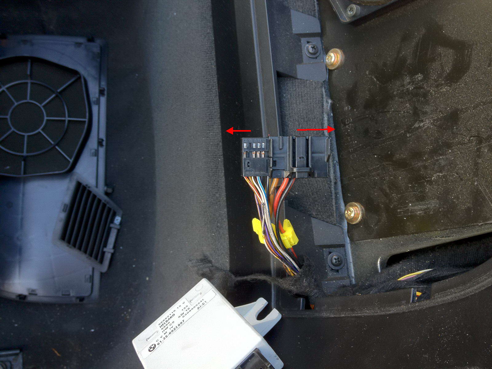
| 6. Now disassemble the black connector by sliding the outer cover off the inner plug. It is latched into place on the left. Lift up the latch while pulling the cap to the right. |
| Installation - Steps 7-9 | |
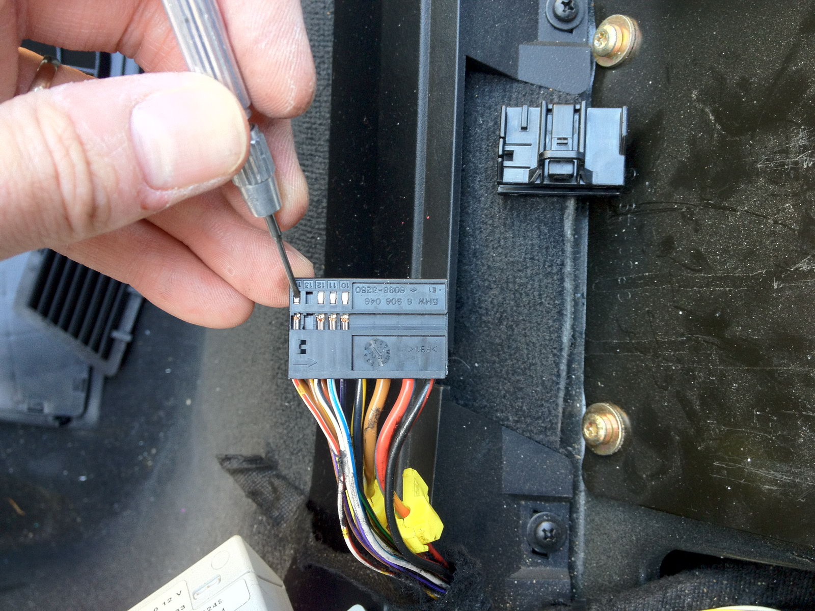
| 7. Remove the wire contact no. 14 from the connector by gently pushing down on the metal latch as shown while pulling on the wire. |
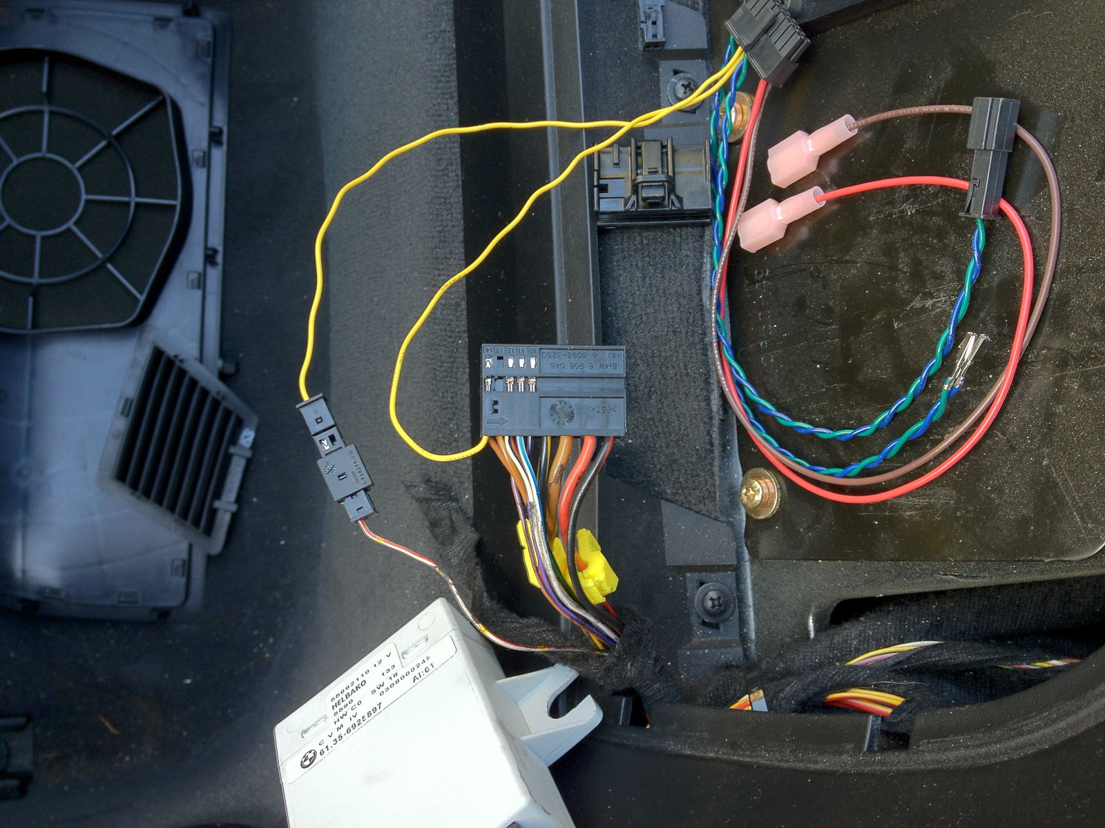
| 8. Take that wire and insert it into position 1 on the small supplied connector cap. Press down hard on the top to engage the plastic locking latch, then connect the cap with the matching one on the wiring harness. Make sure the red/white wire and the yellow wire are on the same side, so they make electrical contact. Now insert the female crimp contact attached to the other yellow wire into the connector in slot 14 to complete the circuit. |
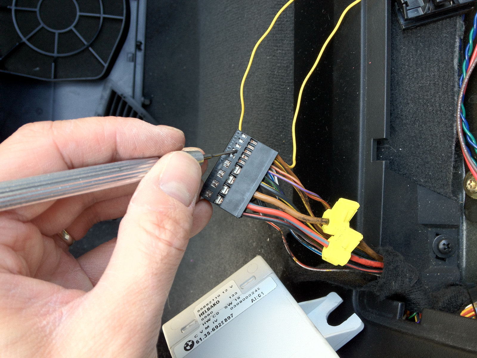
| 9. Remove the purple/brown wire from slot 6 and the red/brown wire from slot 7 in the same way. |
| Installation - Steps 10-12 | |
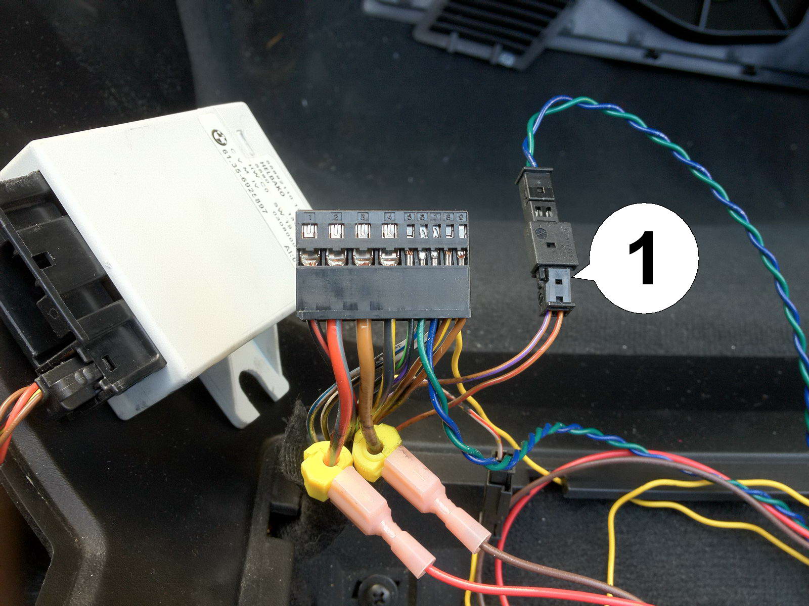
| 10. Insert the purple/brown wire in slot 1 and the red/brown wire in slot 2 of the second small connector cap. Again. press down hard on the latch (1), then mate the connectors as shown. Insert the green wire in connector slot 6 and the blue wire in slot 7 which completes these two circuits. |
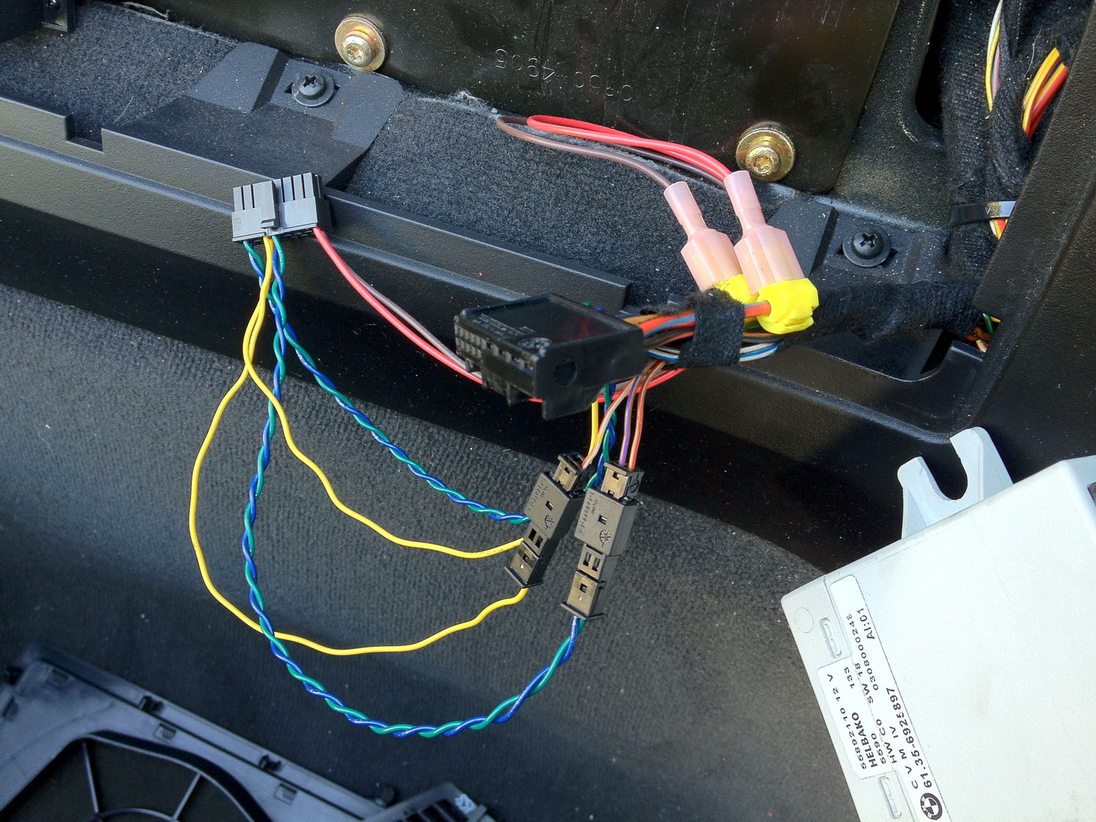
| 11. Now connect the power and ground wires to the yellow taps, re-attach the connector cap and make sure all connections are good. Pull the wiring harness back through to the other opening where it can be connected to the top control unit. |
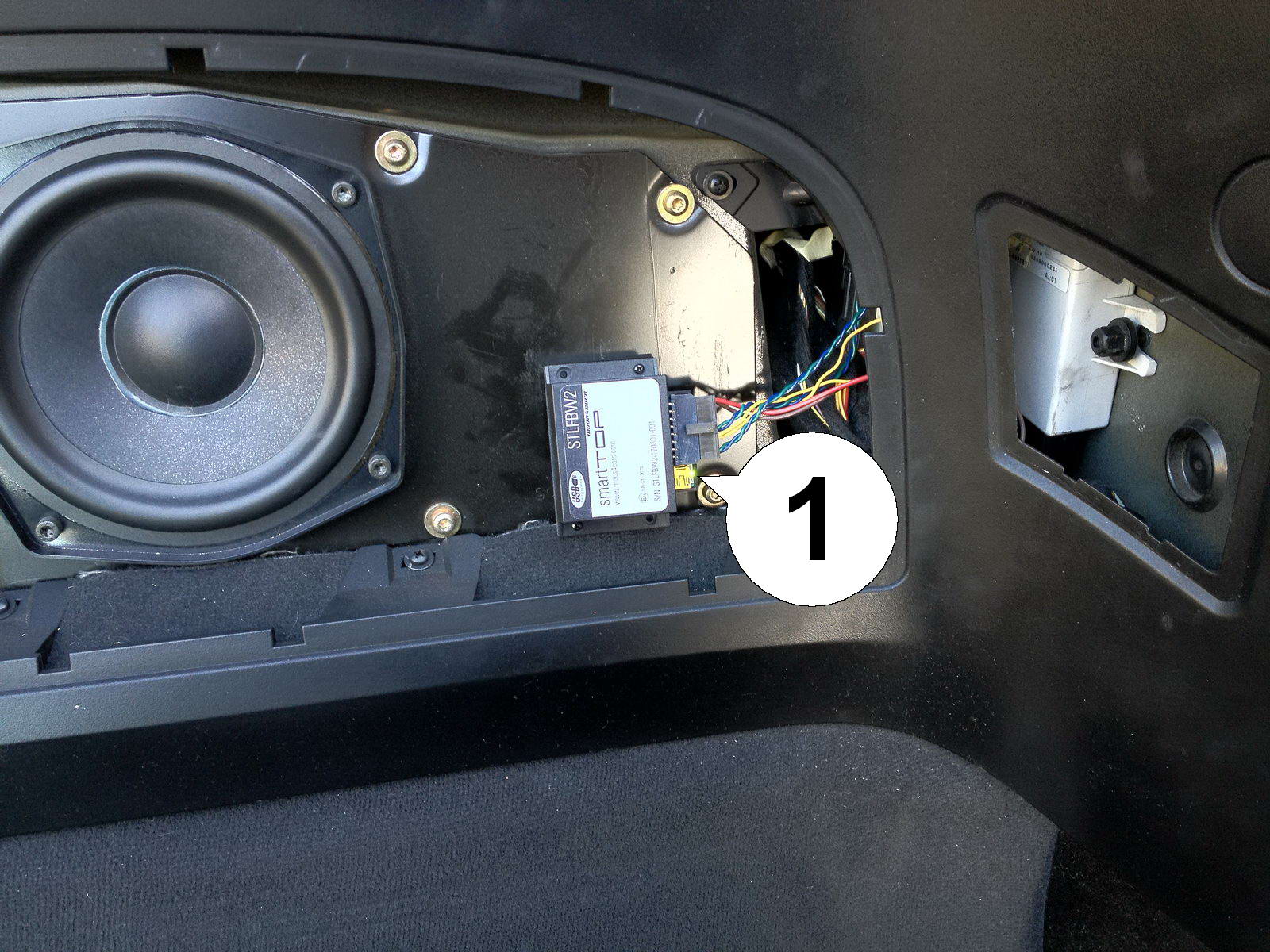
| 12. Put the top control unit back in place and secure it with the nut. Connect the smartTOP module to the wiring harness and use the supplied velcro sticker to attach it securely as shown. Now turn the ignition on and monitor the green LED (1) on the module. It should blink to signal a successful install. Remember to configure the module according to our operation and programming manual. |