INSTALLATION 6 Series (F12)


STHFBW1

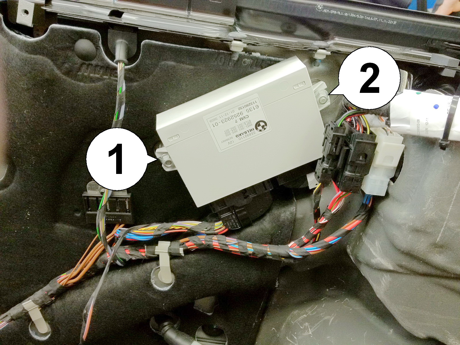
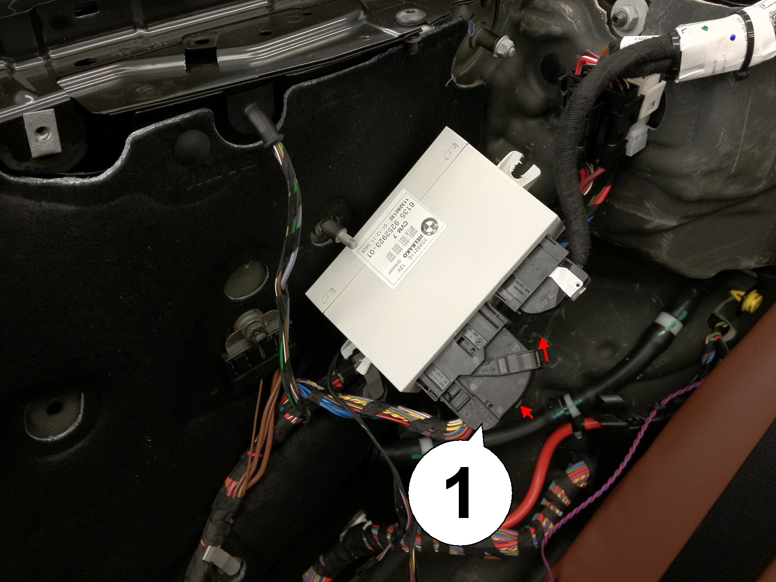
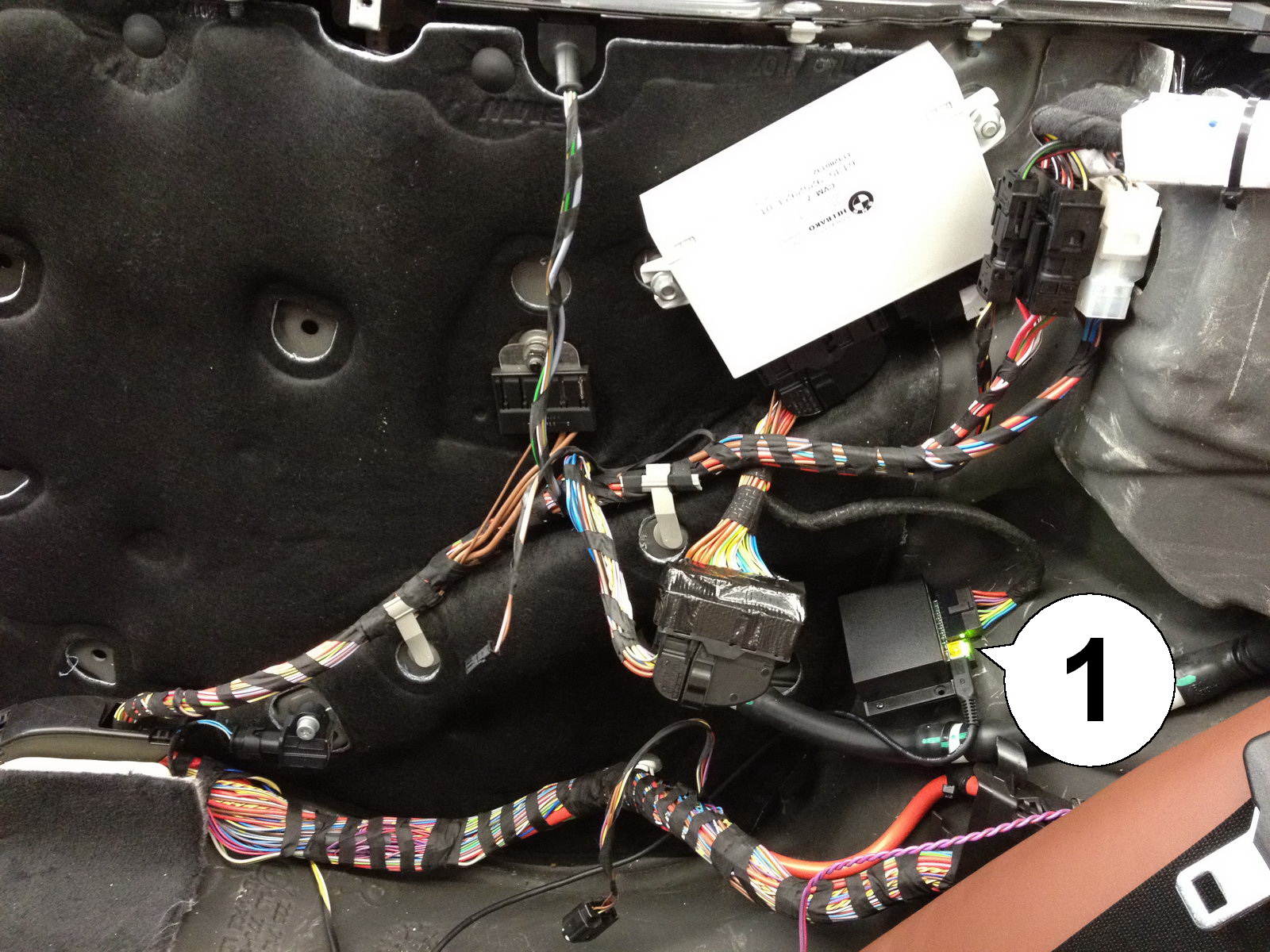
Comfort Roof Control Module for

  • BMW 6 Series Convertible (F12)
  • BMW 2 Series Convertible (F23)

    v1


  • Further information and manuals for all products can be found on our web site

    w w w . m o d s 4 c a r s . c o m

     
    We explicitly point out that all functions of this control unit should be used only while exercising caution and responsibility. We can NOT be held liable for any damage or injury caused by installing or using this product.
    PLEASE READ THE COMPLETE MANUAL CAREFULLY BEFORE USING THIS PRODUCT.
    Important Information. READ BEFORE INSTALLING!
    PRINTING THIS MANUAL
    This manual is designed to produce completely filled pages. In order to get best print results, simply set the borders to minimum settings in the browser's page setup menu and disable headers and footers.

    Activate the print preview and if necessary decrease the zoom level until all pages are shown correctly.

    ALL IMAGES CAN BE CLICKED FOR FULL SIZE in the browser.
    TROUBLE SHOOTING - NEED TO CONTACT US?
    If you run into any problems after installing the module, please go over the manual again in great detail, clicking every photo for full size!
    We now have a full Knowledge Base with Support Ticket system available online at www.mods4cars.com/support

    If you need to contact us, the best and fastest way to do so is by opening a support ticket there

    This module comes with our USB Field Upgrade and Configuration Port! We recommend connecting it to a computer BEFORE YOU INSTALL and using our support app "m4cconnect" to do a quick firmware update check. M4cconnect as well as all other information regarding USB update and configuration can be found at www.mods4cars.com/usb. You can even configure and activate your favorite module functions and settings on screen before the module is installed in the car! It is a good idea to permanently install the USB cable with the module in the car, leaving the computer plug in an easily accessible spot for later use with a Wifi/3G/4G connected laptop.
    IMPORTANT TROUBLESHOOTING TIPS

    If the top does not work properly or at all after installing the module, these tips can be very helpful:

    • 1) Turn Function 1 (Main Switch) off (Setting 0). The module will be completely passive. If the problem still persists and the top won't work, check all connections. Please also check the green DATA LED on the module!

    • 2) Function 2 now has a valet mode (Setting 2) on many modules. Valet mode completely disables opening of the top. Check the setting for function 2 and make sure the module is NOT in valet mode!

    IMPORTANT: Not all modules have the valet mode! Please check the Operation and Programming Manual!
    FUNCTION OF THE DATA LED

    The DATA LED shows the module status and helps troubleshooting issues during installation:

    • When the ignition is ON: The LED should BLINK (flash) in a regular pattern (about 1x per second). This indicates that the module is receiving data and should work OK.

    • When the ignition is OFF: The LED should BLINK (flash) as long as the data bus is still active and turn off after a while (max 5 min) indicating that the car has entered stand-by (sleep) mode.

    • If the LED is permanently lit with the ignition ON, the module is NOT receiving data from the top controller and all connectors should be checked.

    • If the LED does NOT light up at all when turning the ignition ON, the module is either not getting power or not receiving ANY data. All connectors should be checked.
    Installation - Steps 1-3
    1. Start out with the top fully closed. Push and hold the top open switch just until the back of the soft-top and the rear lid are in their upmost positions, then let go and turn the ignition fully off. IMPORTANT: Secure the roof mechanism with either a cardboard box or a piece of wood in the position shown. Otherwise they will sink down over time and block access!
    2. Remove the load-through door in the middle of the back rest by pulling the black lever straight towards the front of the car.
    3. Remove both headrests by pulling up hard, straight up, with a lot of force. They are only snapped into place.
    Installation - Steps 4-6
    4. Lift up the back seat in the front on both sides, then locate the two torx screws in the gap between the seat and the back rest.
    5. Remove the two torx screws on both sides that hold the back rest in place. Lift the back rest up and out toward the front of the car.
    6. Hold the back rest up or temporarily lay it all the way up onto the convertible top. Beginning from the back, lift the bottom seat straight up and wiggle the seat belt buckles free. They tend to get caught and can be freed by trying to lift up the seat at different angles.
    Installation - Steps 7-9
    7. Lift up the rubber seal directly next to the cover flap on the outside of the rear right window trim piece. Carefully pull up and pry the two plastic bolts out of the long holes, then pull the rubber seal (2) completely off the chassis. Now the trim piece should come off easily.
    8. Unhinge the ball joint (1) by pulling hard in the direction of the arrow. Then manually push the cover flap (2) towards the front of the car. Remove the torx screw (3).
    9. Remove the 8mm nut (1) that holds the quarterpanel in place.
    Installation - Steps 10-12
    10. Now remove the right door entry trim piece by pullig up hard, beginning from the front and working toward the back. It is only snapped into place.
    11. Here the plastic snap bolts can be seen that hold the door trim piece. The last one is up around the corner, which makes it necessary to first pull the trim piece up in the front.
    12. Remove the screw inside the air deflector fastening hole.
    Installation - Steps 13-15
    13. Now the entire quarterpanel can be flipped open. Starting on the top, pull hard towards the center of the car. Note the 3 metal clips that hold it in place on the top. Also visible here are the grey snapping bolts, a blue one and a yellow one in the back. Disconnect the speaker and lighting cables and lift the panel out.
    14. Behind the panel is the white top controller module (CVM). Remove the left nut (1) and loosen the right one (2), then pull the control unit out.
    15. Disconnect the large plug (1) by pushing in the locking tab while flipping the locking lever over to the right. This automatically ejects the plug.
    Installation - Steps 16-18
    16. Connect the plug to the matching socket on the SmartTOP wiring adapter. Make sure the locking lever is flipped back up and latches into place.
    17. Connect the wiring adapter to the top control unit and mount it again with the two nuts. Now connect the SmartTOP module and tap the unlock button on the remote once. The green LED (1) on the module should now blink to indicate correct installation and data bus activity.
    18. We suggest connecting the supplied USB cable to the module and running it to an accessible spot, e.g. under the back seat. This allows easy access with a laptop at a later time to install firmware updates or to conveniently configure the module settings. Assemble everything in reverse order and configure the module according to our Operation and Programming Manual.